Maximizing overall equipment effectiveness (OEE) across multi-tier canning operations necessitates robust specifications for the High-Speed Fish Heading Gutting Tailing Machine. When integrated alongside a turnkey high-speed sardine and mackerel canning plant integration, this unit maintains tight operating tolerances and repeatable performance across diverse container formats.
This technical engineering brief analyzes the mechanical design criteria, operating equations, MEP utility requirements, failure mode diagnostics, and quality validation protocols governing the High-Speed Fish Heading Gutting Tailing Machine in modern automated canning lines, with dedicated focus on Mass Flow Kinematics & Sizing (Production Capacity Sizing and Line Balancing).
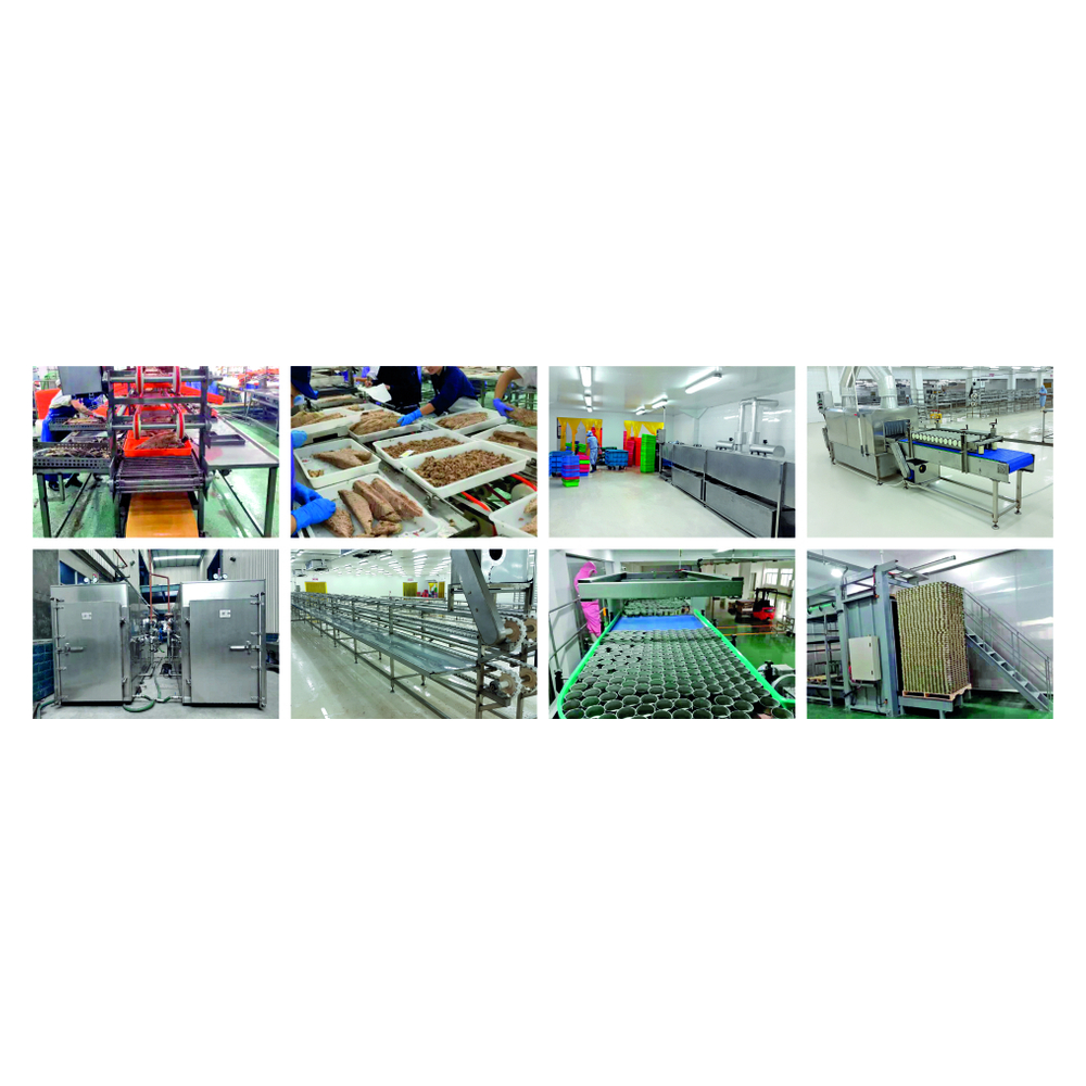
1. Production Capacity Sizing and Dynamic Line Balancing Analysis
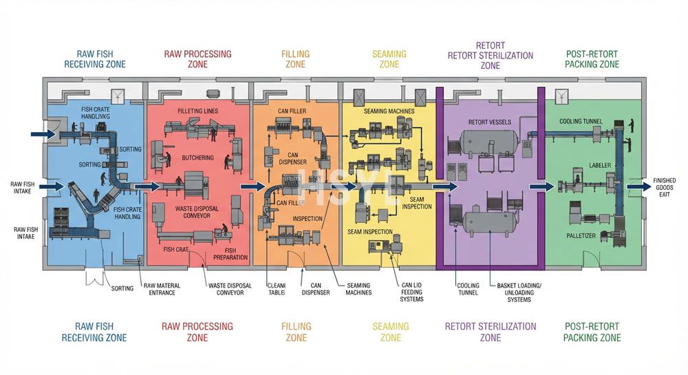
Achieving stable high-efficiency output across automated canning lines requires systematic capacity sizing and line balancing for the High-Speed Fish Heading Gutting Tailing Machine. When integrating this machinery into the Sardine & Mackerel Canning Line, process engineers calculate instantaneous and surge throughput capacities to eliminate upstream accumulation and downstream starvation.
The operational throughput rating is determined by container travel kinetics, machine indexing pitch, and fluid/product transfer velocities. In commercial canneries operating between 60 and 500 cans per minute (cpm), capacity balance is governed by the Mass Flow Rate Equation:
Continuous Cannery Mass Flow Rate Equation:
Q_cpm = (V_belt * 60) / (D_can + S_clearance) * eta_line
Where V_belt is linear transfer speed (m/s), D_can is nominal outer can diameter (m), S_clearance is dynamic inter-can safety gap (0.015-0.030 m), and eta_line is operational efficiency (0.92-0.96).
To prevent line stoppage during downstream seamer tool index changes or retort basket transfers, an integrated accumulation buffer table must provide a minimum of 2.5 to 4.0 minutes of continuous line surge buffering. Dynamic line balancing ensures overall equipment effectiveness (OEE) exceeds 88% across multi-shift production cycles.
2. Rotary Tool Metallurgy and Shear Geometry
Cutting and deboning tools are CNC-machined from cryogenically hardened AISI 440C martensitic stainless steel (Rockwell C 58-62). Ultra-fine edge geometry produces clean cellular cleavage without bruising or thermal friction denaturation.
The structural assembly is constructed from high-tensile sanitary stainless steel, designed to withstand rigorous caustic washdown environments while maintaining precise axis alignment across high-duty operational shifts.
3. Kinematic Drive and Vibration Suppression
Direct-coupled brushless servo drives eliminate backlash and belt slippage. Dynamic harmonic dampers mounted on solid cast 304 chassis absorb cyclic torque spikes during heavy mechanical impact.
To sustain synchronized production without line starvation, downstream integration is streamlined by connecting with certified automatic retort basket unloading and container sweep system systems.
4. Engineering Specifications and Operating Envelope
Factory-calibrated performance parameters for standard and high-throughput industrial operations:
| Engineering Parameter | Standard Operating Baseline | Heavy-Duty Industrial Rating |
|---|---|---|
| Equipment Construction | AISI 304 frame, 380V-415V 3-phase (4.5-7.5 kW), 800-1500 kg/h raw feed rate, IP66 washdown | AISI 316L product contact, 380V (11.0-18.5 kW), 2500 kg/h continuous industrial rating, IP69K rated |
| Primary Electrical Feed | 3-phase 380V-415V 50/60 Hz with dedicated line filter to suppress VFD harmonics. | Dedicated isolator switch with transient surge suppression |
| Hydraulic & Utility Supply | Cold sanitizing washdown water (DN20, 0.3-0.5 MPa) with food-grade foam injector connection. | Stainless steel manifold with sanitary isolation valves |
Foundation specifications require a reinforced concrete slab (minimum C30/37 structural grade) equipped with high-density anti-vibration elastomeric isolation mounts, isolating dynamic cyclic harmonics from adjacent cannery floor cells. The machine operating envelope supports continuous processing in ambient temperatures from +5 deg C to +45 deg C with relative humidity up to 95% non-condensing. All on-board control enclosures are rated to IP69K stainless construction with active internal vortex cooling manifolds to prevent moisture condensation during intensive high-pressure washdown shifts.
5. Engineering Principle & Analytical Sizing Model
Process modeling and capacity calculation adhere to verified thermodynamic and kinetic equations:
Mechanical Shear Yield & Throughput Equation:
Mass Throughput (kg/h) = [Spindle RPM * Tool Pocket Count * Unit Mass (kg) * Cutting Efficiency Factor (0.94)] / 60
Practical Calculation: For a dual-shaft cutting and deboning station running at 180 RPM with 8 pocket flutes: Throughput = 180 * 8 * 0.45 * 0.94 / 60 = 10.15 kg/min (609 kg/h net recovery rate with flesh loss strictly under 3.2%).
Adhering to this mathematical model allows project engineers to accurately size upstream batch buffers and downstream conveyance without risking product accumulation or thermal degradation. Finite element stress simulations (FEA) and computational fluid dynamics (CFD) validate that mechanical deflections remain under 0.015 mm under peak line surges, preserving continuous mass-balance equilibrium and preventing container deformation during high-speed transfer operations.
6. Failure Mode and Effects Diagnostics (FMEA)
Critical operational fault signatures, root-cause pathways, and field remediation actions:
| Operational Fault Signature | Probable Root Cause | Field Corrective Action |
|---|---|---|
| Cutting Edge Chipping | Foreign metallic inclusion or frozen product core exceeding hardness threshold | Install upstream 3000 Gauss magnetic trap; check raw product core temp >= -2 deg C. |
| Excessive Product Flesh Loss (>5%) | Worn counter-shear anvil clearance; guide plate gap drift exceeding 0.15 mm | Recalibrate blade-to-anvil clearance using feeler gauges to exactly 0.08-0.12 mm. |
| Spindle Bearing Temperature High (>65 deg C) | Grease emulsification from high-pressure sanitizing washdown | Replace with double-sealed PTFE sanitary bearing cartridge; replenish NSF H1 food grease. |
7. Preventative Maintenance and Commissioning Spares Strategy
To preserve line efficiency and achieve planned preventative maintenance objectives:
- Daily Inspection Protocol: Clean product-contact zones with neutral detergent; inspect pneumatic seals and line strainers; record operating pressures.
- Monthly Lubrication & Calibration: Replenish NSF H1 food-grade grease in sealed bearing housings; calibrate sensor switching thresholds; check drive chain tension.
- Critical Spares Kit on Hand: Maintain on-site: Set of precision rotary blades (440C), 2 sets of anvil guide wear plates, 4 sanitary scraper seals.
- Annual Overhaul & Dynamic Laser Alignment: Perform precision laser shaft alignment and dial-indicator spindle runout verification (maintaining total radial deflection strictly under 0.025 mm). Execute acoustic vibration spectral FFT analysis per ISO 10816-3 Class II industrial standards to detect early bearing raceway micro-spalling before catastrophic fatigue occurs.
For end-of-line secondary handling and packing automation, explore our complementary sanitary food and beverage can conveying systems.
8. Sanitary Hygiene Engineering & Regulatory Compliance Protocols
Industrial canning lines must comply with rigorous international food safety standards, including FDA 21 CFR Part 113 for low-acid canned foods, European EHEDG guidelines, and 3-A Sanitary Standards. Contact parts manufactured from AISI 316L stainless steel undergo electrolytic polishing to achieve surface finishes below Ra 0.8 micrometers, eliminating microscopic crevices that harbor bacterial biofilm.
Automated Clean-in-Place (CIP) and Steam-in-Place (SIP) routines are integrated directly into the machine control architecture. Automated sequencing controls deliver a 5-stage cleaning cycle: initial warm water pre-rinse, circulating caustic wash (1.5-2.0% NaOH at 75-85 deg C) with turbulent flow velocities exceeding 1.5 m/s, intermediate potable water rinse, nitric acid neutralization flush (0.8-1.2% HNO3 at 60 deg C) to remove mineral scale, and final cold sanitizing rinse. Digital conductivity probes and flow transmitters continuously verify chemical concentration and turbulent velocity, generating encrypted audit logs required for third-party BRCGS and IFS Food safety certifications.
Every unit supplied by HSYL undergoes exhaustive Factory Acceptance Testing (FAT) before shipment. Verification packages include full Installation Qualification (IQ) and Operational Qualification (OQ) protocols, material test reports (EN 10204 3.1 certification), weld inspection records, and calibrated thermal and dimensional validation certificates ensuring immediate, compliant commissioning on the cannery plant floor.
Related Articles

Get professional consultation
Do you have any questions or need technical support regarding the content of this article? Fill out the form below, and our expert team will provide you with professional solutions.