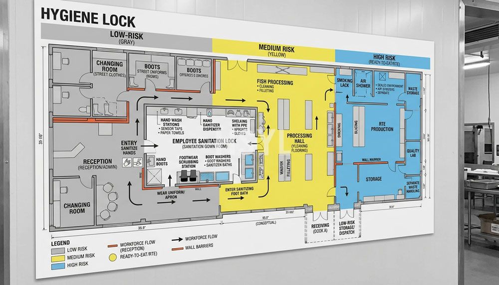
Hygienic Zoning: The Physical Boundary Principle
In industrial seafood processing, the floor layout is the primary barrier against biological contamination. Plant engineers must implement a strict zoning model, dividing the facility into low-care (wet prep), medium-care (pre-cooking and filling), and high-care (post-sealing and retorting) zones. This physical separation prevents raw materials, which carry high initial microbial loads, from contacting processed, sterile cans.
At the raw receiving area, fish are unloaded, graded, and stored in chilled water tanks. The layout here must accommodate heavy water usage and high organic waste. The floor should slope at a minimum of 1:50 toward stainless steel slot drains to prevent any standing water. Pooling water is a primary reservoir for pathogens like Listeria monocytogenes, which can easily colonize wet concrete floors.
As the fish move from grading to evisceration, the waste must be removed immediately. We design the evisceration layout with under-floor vacuum extraction pipes or closed screw conveyors. This setup eliminates the need for open waste flumes, which release aerosolized bacteria into the room. Ambient air handling systems must maintain negative pressure in this raw prep zone, ensuring that air flows from the clean filling rooms outward to the raw handling dock.
To comply with food safety standards, employees must access different zones through dedicated hygiene locks. These stations require sole-washing machines, hand-sanitation turnstiles, and dedicated footwear transitions. By embedding these locks directly into the layout walls, plant managers eliminate the risk of operators carrying raw-zone contaminants into the sterile processing areas. The baseline guideline for these setups is defined in the FDA Seafood HACCP regulations.
Thermal Processing and the Pre-Cooking Bottleneck
Pre-cooking is the critical step that defines the texture, moisture content, and final yield of canned fish. Whether processing sardines, mackerel, or tuna, the fish must be heated to release moisture and coagulate proteins before sealing. However, pre-cooking is traditionally a batch or semi-continuous process, which introduces flow variability into an otherwise continuous packaging line.
When planning the layout, the pre-cooking tunnel requires significant physical space and substantial utility connections. High-pressure steam lines, condensate return pipes, and heavy-duty exhaust hoods must be integrated into the ceiling layout. Poor steam exhaust design leads to condensation dripping from the ceiling onto open product lines, a serious compliance violation.
We manage the batch-to-continuous transition by installing automated cooling and buffer zones immediately after the pre-cooker. After exiting the steam tunnel, the hot fish must be cooled rapidly to halt the cooking process and firm the flesh for slicing and packing. The layout must allocate sufficient floor space for cooling conveyors or vacuum cooling chambers. If cooling is too slow, the fish flesh breaks during packing, resulting in high flake content and reduced premium pack yield.
For high-capacity operations, we suggest using an automatic fish canning production line. This setup integrates the pre-cooker discharge directly with automated rotary fillers. Automation reduces operator dependency, stabilizes packing weight accuracy, and improves overall line yield.
Automation vs. Manual Labor in Processing Layouts
When designing the pre-processing and filling zones, engineers face a major trade-off: automated machinery versus manual trimming and packing. In markets with low labor costs, manual packing tables are often preferred due to lower capital cost. However, manual packing requires a significantly larger footprint. A manual packing table for 30 operators requires about 15 meters of linear floor space, excluding the clearance space needed for operators, product supply bins, and raw waste collection carts.
This large manual footprint increases the clean-room size, which directly raises the installation and operating costs of the HVAC air handling systems. Furthermore, manual packing tables introduce significant hygienic risks. Every operator contact increases the potential for microbiological contamination. In contrast, automated pocket fillers pack fish chunks into cans with minimal contact, using high-speed mechanical indexing to achieve throughputs of up to 250 cans per minute in a footprint of just 4 square meters.
Automated filling systems also drastically reduce product giveaway. A manual packer might overfill a can by 2 to 5 grams to ensure compliance with net weight regulations. While this seems minor, on a line running 100,000 cans per day, a 3-gram average overfill translates to 300 kilograms of lost raw material daily. At current seafood market prices, this yield loss can quickly erase the initial capital cost savings of manual labor within a single operating season.
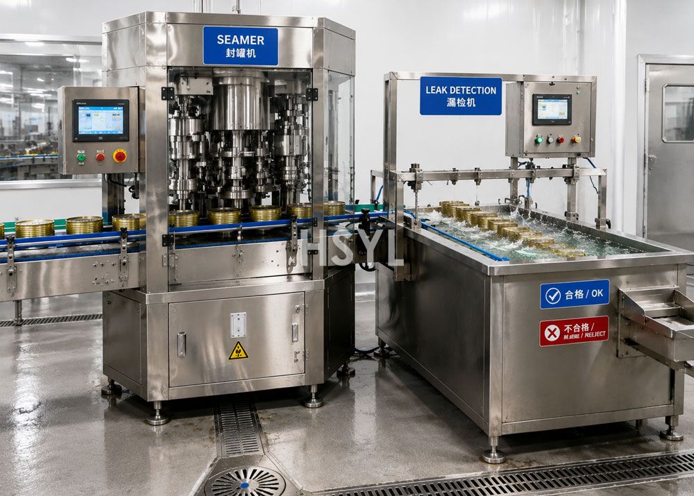
Line Balancing: Calculating Buffer Capacity
A common error in fish canning factory layouts is the lack of buffer capacity between the filling station and the double seamer. The double seamer is the most sensitive machine on the line, operating at high speeds. If a seamer stops due to a jammed can or a lid feed issue, the entire upstream filling and pre-processing line will halt if there is no accumulation capacity.
We calculate accumulation conveyor requirements using a simple formula based on throughput and recovery time. If the line runs at 120 cans per minute, and the average operator response time to clear a minor seamer stoppage is 3 minutes, the buffer system must accommodate at least 360 cans. This is achieved using multi-way bi-directional accumulation tables or vertical spiral conveyors.
Conveyor transitions between the filler and the seamer must be smooth and linear. Any sudden changes in speed or direction will cause liquid spillage, especially when filling fish in oil or brine. Spilled oil on the can flange prevents a clean double seam, leading to seal failure during retorting. Therefore, all conveyors in this section must be driven by variable frequency drives (VFDs) configured to accelerate and decelerate gradually.
Clean-in-Place (CIP) and Utility Distribution Layout
A high-performance layout must accommodate the routing of clean-in-place (CIP) lines, chemical distribution pipes, water lines, and compressed air systems. The CIP station itself should be located centrally to minimize the run lengths of piping. Long CIP piping runs lead to heat loss, pressure drops, and increased chemical waste during rinsing phases. The batched chemical tanks must be located in a containment dike with proper ventilation to handle acid and caustic fumes safely.
During the cleaning workflow, the line is divided into hygienic circuits. The raw prep conveyors, pre-cooker internals, sauce batching tanks, and volumetric fillers are cleaned in sequence. In the layout, we specify dedicated piping manifolds at each machine to allow rapid connection to the central CIP loop. This modular sanitation design reduces changeover time and ensures consistent, validated cleaning protocols that satisfy global food safety standards.
Utility drops from the ceiling should use stainless steel utility headers rather than flexible hoses. Flexible hoses running along the floor create trip hazards for operators and trap water, forming breeding grounds for bacteria. By routing all electricity, steam, water, and compressed air vertically from overhead utility racks down to the machines, engineers keep the floor clear, facilitating rapid washdowns and visual inspection during shifts.
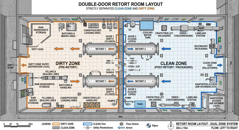
The Retort Room: Traffic Flow and Safety
The retort room is the thermal sterilization zone where the canned fish achieves commercial sterility. Because this area handles both unsterilized (raw-filled) and sterilized (finished) cans, the layout must prevent any possibility of product mix-ups. A single unretorted can entering the packaging warehouse can lead to botulism outbreaks and catastrophic product recalls.
To enforce safety, the retort layout must utilize a straight-line flow with a physical barrier separating the loading and unloading zones. Double-door (pass-through) retorts are ideal for this application. Unprocessed baskets enter from the loading side, the sterilization cycle runs, and the baskets exit from the opposite side into the clean cooling and packaging area.
If single-door retorts must be used due to space constraints, we implement a strict color-changing chemical indicator tape system on every basket. Furthermore, the layout must include physical gates that only open when a retort cycle completes, guiding the processed baskets to the unloading station. In our custom designs, such as the turnkey fish canning line, we utilize automated retort basket loaders and unloaders. This mechanical handling system reduces labor costs and minimizes can denting, which can occur during manual loading. Dented cans often suffer from seam failure during the high-pressure sterilization cycle.
Structural Engineering: Drains, Slopes, and Foundations
Seafood processing plants are among the most corrosive environments in the food industry. Fish proteins, salt, oils, and harsh cleaning chemicals like sodium hydroxide quickly degrade standard building materials. The structural design of the floor and foundations must be completed in tandem with the equipment layout.
All process machinery should be elevated on concrete plinths with rounded edges to prevent dirt accumulation. The double seamer, which weighs several tons and operates with reciprocating mechanical parts, requires a dedicated, vibration-isolated foundation. If the seamer is bolted directly to the general floor slab, structural vibrations will travel back to the filling machines, causing inconsistent fill weights and seam variations.
Floor drainage is another critical element. We recommend stainless steel slot drains over box drains. Slot drains are easier to clean and do not collect large volumes of stagnant water. The drainage piping under the floor must be constructed of chemical-resistant materials like high-density polyethylene (HDPE) or acid-grade stainless steel to withstand the hot, corrosive cleaning chemicals discharged during Clean-in-Place (CIP) cycles.
Comparing Layout Strategies
Choosing the right layout configuration depends on your factory footprint and utility connection points. The table below compares the three most common floor plans for fish canning lines.
| Layout Pattern | Footprint Requirements | Sanitation Access | Flow Control | Expansion Capability |
|---|---|---|---|---|
| Linear (Straight) | Long, narrow space | Excellent (open on both sides) | Direct (ideal for straight conveyor runs) | Poor (requires building extension) |
| U-Shape | Square or wide room | Moderate (center is crowded) | Good (shared raw/pack loading bays) | Excellent (can extend the bottom loop) |
| L-Shape | Corner space or angled building | Good | Moderate (90-degree transfers required) | Moderate |
We generally recommend the linear layout for new greenfield plants. It provides the cleanest separation of sanitary zones. However, for existing buildings with limited length, a U-shape layout allows the sharing of raw receiving and finished goods shipping docks, saving space and reducing structural costs.
Act-Now Optimization Checklist for Plant Engineers
If you are experiencing low line efficiency or hygiene issues in your current setup, perform the following audits on your floor plan:
- Check the floor slope: Confirm that the floor slopes at least 1:50 toward the drainage channels. Standing water in the prep zone is a primary source of Listeria.
- Measure buffer conveyor capacity: Calculate if your accumulation system can hold at least 5 minutes of maximum throughput. If not, add modular belt loops.
- Inspect double seamer isolation: Verify that the seamer is bolted to a reinforced concrete block separated from the main floor slab by elastomeric damping pads.
- Verify air flow direction: Ensure air flows from the filling room (high hygiene) toward the raw prep room (low hygiene), never the reverse.
Real-World Layout Implementation
We designed a customized layout for an integrated seafood canning plant. In that project, the local factory space was limited in length but had high ceilings. We resolved this by installing an elevated mezzanine for the empty can depalletizers and gravity feed chutes. This footprint optimization saved 120 square meters of floor space and kept empty cans away from the wet processing floor.
Related Topics
- Small-Scale Fish Canning Line Options
- Sourcing a Turnkey Fish Canning Plant: B2B Procurement Guide
- Calculating Fish Canning Line Cost: B2B Engineering Guide
Optimize Your Seafood Processing Layout
Designing a factory floor that balances high-speed seaming with complex thermal processes requires deep engineering experience. Our technical consultants are ready to review your floor plans, calculate line balancing buffers, and configure equipment to match your target throughput. Contact HSYL today to discuss your next production line layout.
Frequently Asked Questions
What is the typical footprint required for a 20000 can per day fish canning line?
How do you prevent cross contamination between raw prep and post retort zones?
Should we use an atmospheric or vacuum seamer for canned tuna?
What is the standard lead time for HSYL turnkey seafood canning lines?
Can a sardine canning line be repurposed for mackerel?
How is cleaning handled in a wet fish processing environment?
What slope is recommended for the factory floor to ensure proper drainage?
Related Articles


Get professional consultation
Do you have any questions or need technical support regarding the content of this article? Fill out the form below, and our expert team will provide you with professional solutions.