The croissants came out of the oven at 7:42 on a Tuesday morning with bottoms barely colored while the tops were already past golden. The digital display read 180 degrees Celsius. The dial was set to 180 degrees Celsius. The probe thermometer hanging inside the chamber read 162 degrees Celsius. Three readings, three different numbers, and a batch of laminated pastry that had to be sold at half price or discarded. That single batch represented two hours of proofing, forty minutes of laminating, and roughly forty dollars of butter — lost not to a recipe failure but to a temperature control problem that no one had noticed because the display still showed a number that looked correct.
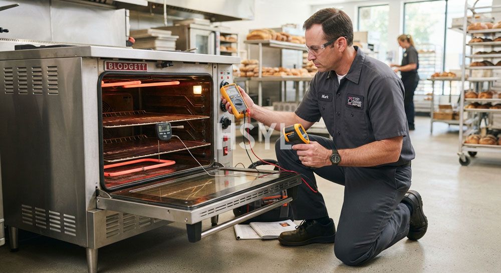
Commercial oven temperature control problems rarely announce themselves. They appear first as a slightly longer preheat, then as a batch that needs an extra five minutes, then as a baker who quietly adjusts the dial upward by ten degrees to compensate, then as a customer complaint about inconsistent texture, and finally as a service call that reveals the oven has been operating fifteen to twenty degrees off its setpoint for months. By the time the discrepancy becomes obvious, the cumulative cost in wasted product, energy, and staff time has already exceeded the cost of the repair many times over.
This guide walks through the diagnostic discipline that distinguishes a controlled bakery operation from one that depends on luck. It covers the six most common temperature control symptoms in commercial electric ovens, the equipment checks that identify the root cause for each, and the preventive schedule that keeps temperature drift from recurring. The framework applies to deck ovens, convection ovens, and combi ovens used in bakeries, hotel pantries, and central kitchens. For broader equipment selection context, see HSYL Full View Electric Oven as the reference platform for the diagnostic checks described below.
1. Why Temperature Control Is the Single Variable That Determines Oven Value
Every other capability of a commercial oven — its deck capacity, its power rating, its construction quality, its certifications — matters only insofar as the oven can deliver a specified temperature accurately and consistently. An oven that cannot hold 220 degrees Celsius within a tight band is not a commercial oven regardless of its stainless steel grade or its CE marking. It is an expensive heating box that produces inconsistent product.
Temperature control problems impose three categories of cost that operators routinely underestimate:
| Cost Category | How It Manifests | Typical Magnitude |
|---|---|---|
| Product Yield Loss | Over-baked batches discarded, under-baked batches reworked or sold at discount, laminated pastry ruined by butter leakage when oven overshoots, bread with poor oven spring when oven underheats | 3 to 8 percent of daily baking output lost to temperature-related defects in uncontrolled ovens |
| Energy Waste | Heating elements cycling longer to compensate for door seal leaks, oven running ten degrees hotter than necessary because operator overcompensates for perceived cold, recovery time extended by degraded element performance | 10 to 20 percent additional energy consumption per cycle in ovens with unresolved control issues |
| Recipe Drift and Quality Variability | Same recipe producing different results across batches and shifts, bakers unable to diagnose defects because the oven is the uncontrolled variable, customer complaints about texture or appearance that cannot be traced to ingredient or process | Difficult to quantify but typically the largest single cost over time through customer retention impact |
Engineering Note: A commercial oven that operates within plus or minus 5 degrees Celsius of setpoint across the entire deck surface, cycle after cycle, is the baseline expectation for professional baking. Better units achieve plus or minus 3 degrees. An oven operating outside this band is not a commercial oven operating poorly — it is a commercial oven failing its core function. Treat any sustained deviation greater than 8 degrees as a defect requiring diagnosis rather than a quirk to be worked around by adjusting the dial.
2. Symptom-to-Cause Classification: Where Diagnosis Starts
Effective oven diagnosis begins with observing the symptom precisely rather than reaching for the most familiar fix. The same observed problem — for example, uneven baking — can originate from a faulty heating element, a degraded door seal, a calibration drift, or an air circulation issue. Each cause requires a different repair, and applying the wrong fix wastes time and money without resolving the underlying problem.
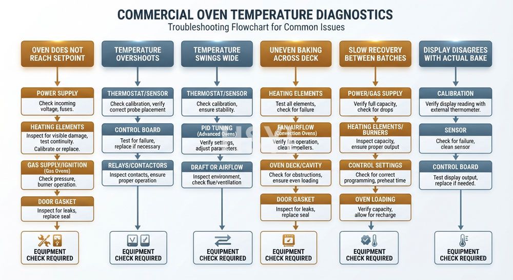
The table below maps the six most common temperature control symptoms to their likely root cause categories. Use this table as the starting point for diagnosis, then proceed to the specific equipment checks described in the following sections.
| Observed Symptom | Likely Root Cause Category | Initial Equipment Check | Severity |
|---|---|---|---|
| Oven does not reach set temperature | Heating element partial failure, voltage supply drop, thermostat or sensor drift, control board fault | External thermometer test to verify actual chamber temperature against display reading | High — directly stops production |
| Oven temperature overshoots setpoint | Thermostat calibration drift upward, temperature sensor degraded, control relay stuck closed, inadequate ventilation causing heat accumulation | External thermometer test at multiple chamber locations, observe heating element cutoff behavior | High — ruins delicate products, fire risk at extreme overshoot |
| Temperature swings too wide (cycling hysteresis) | Thermostat hysteresis band too wide, sensor location poor, control board programming issue, thermal mass insufficient | Log temperature at one-minute intervals across a complete heating cycle to measure hysteresis band | Medium — affects consistency, not raw throughput |
| Uneven baking across deck (hot spots, cold corners) | Individual heating element failure, air circulation fan issue, deck surface unevenness, reflector panel damage, oven leveling off | Bread flour or sugar test to map hot spots across deck surface | High — destroys batch consistency |
| Slow temperature recovery between batches | Heating element degradation, insufficient power capacity, door seal leak allowing heat loss, excessive door opening frequency | Time the recovery from 180 to 220 degrees with door closed, compare to manufacturer specification | Medium — extends production window |
| Display reading disagrees with actual baking result | Sensor calibration drift, sensor location unrepresentative of baking zone, control board error, sensor wire resistance change | External probe thermometer comparison test at sensor location and at baking deck level | High — operator loses trust in oven, compensates incorrectly |
Diagnostic Discipline: Resist the temptation to begin with the fix you know how to perform. A baker who is comfortable replacing heating elements will diagnose every temperature problem as a heating element failure, while a baker experienced with calibration will diagnose every problem as calibration drift. Both will be wrong approximately 60 percent of the time. Begin with the symptom observation, narrow to root cause through the equipment checks below, and only then perform the repair that the diagnosis actually justifies.
3. Equipment Check One: Calibration Verification
Calibration drift is the single most common cause of commercial oven temperature problems, accounting for roughly 35 to 45 percent of all diagnosed cases. Drift occurs gradually as the temperature sensor ages, as thermal cycling stresses the sensor element, and as the control board's reference voltage shifts over years of operation. A typical commercial oven drifts 5 to 10 degrees from its original calibration after 12 to 18 months of daily use, and continues drifting at approximately 3 to 5 degrees per year thereafter.
The challenge with calibration drift is that the oven display continues to show whatever setpoint the operator enters — the display reflects what the oven believes it is doing, not what the chamber actually is. Without an independent reference measurement, drift can persist undetected for months.
External Thermometer Calibration Test
This test requires an independent reference thermometer rated for oven temperatures. A laboratory-grade digital probe thermometer with a thermocouple rated to 400 degrees Celsius is the appropriate tool. Infrared thermometers are not suitable for this test because they measure surface temperature, not air temperature, and are affected by surface emissivity.
- Allow the oven to fully preheat: Set the oven to 180 degrees Celsius and allow at least 45 minutes of preheat time after the indicator shows the oven has reached setpoint. The full thermal mass of the deck and chamber walls must stabilize, not just the air temperature. A preheat that ends when the display first reaches 180 degrees typically leaves the actual chamber 10 to 15 degrees below setpoint.
- Position the probe at baking deck level: Suspend the probe thermometer at the height where product actually bakes — typically 30 to 50 millimeters above the deck surface for deck ovens, or at the center of the middle rack for convection ovens. Do not measure at the top of the chamber near the ceiling, where temperatures run higher than at baking level.
- Allow 10 minutes of stabilization: Opening the door to insert the probe releases heat and disrupts the equilibrium. Allow the oven to recover for 10 minutes with the door closed before recording the probe reading.
- Record the reading: Note the probe temperature and compare to the display setpoint. A reading within plus or minus 5 degrees of setpoint is acceptable. A reading 6 to 10 degrees off warrants recalibration. A reading more than 10 degrees off requires either recalibration or sensor replacement depending on whether the drift is consistent across multiple setpoints.
- Repeat at three setpoints: Test at 150, 200, and 250 degrees Celsius. If the offset is consistent across all three setpoints (for example, the oven reads 12 degrees low at every setpoint), the calibration is uniformly shifted and recalibration will resolve the issue. If the offset varies across setpoints (for example, 5 degrees low at 150 but 18 degrees low at 250), the sensor itself is degraded and replacement is required.
Calibration Note: Many commercial ovens including the HSYL Full View Electric Oven line provide a calibration offset adjustment accessible through the control panel or service menu. This offset allows the operator to add or subtract a fixed number of degrees to correct uniform drift without replacing components. Consult the specific model's service manual for the offset adjustment procedure. If the drift exceeds the maximum offset range (typically plus or minus 20 to 30 degrees), sensor replacement is required rather than recalibration.
4. Equipment Check Two: Heating Element Diagnosis
Heating element failure accounts for approximately 25 to 30 percent of commercial oven temperature problems. Failure modes range from complete burnout (the element produces no heat at all) to partial failure (one of multiple elements fails, producing uneven heating) to gradual degradation (the element produces reduced output as internal resistance increases over its service life).
Electric heating elements in commercial ovens typically have a service life of 2 to 4 years under daily operation, with longer life in ovens operated at lower average temperatures and shorter life in ovens operated continuously near maximum rated temperature. Elements fail most commonly at the terminal connections where thermal cycling causes metal fatigue, and at internal welds where the heating wire joins the terminal pin.
Heating Element Resistance Test
This test requires a digital multimeter capable of measuring resistance in the 10 to 100 ohm range. The test verifies that each heating element produces the resistance corresponding to its rated wattage at the supply voltage, identifying both complete failures and partial degradations.
| Element Rated Wattage at 220V | Expected Resistance (ohms) | Multimeter Reading Interpretation |
|---|---|---|
| 1,500 W | Approximately 32 ohms | Within plus or minus 10 percent: healthy. Significantly higher: degraded. Infinite (open circuit): burned out. |
| 3,000 W | Approximately 16 ohms | Within plus or minus 10 percent: healthy. Significantly higher: degraded. Infinite (open circuit): burned out. |
| 4,500 W | Approximately 11 ohms | Within plus or minus 10 percent: healthy. Significantly higher: degraded. Infinite (open circuit): burned out. |
| 6,000 W (typically 380V three-phase) | Approximately 24 ohms per phase | Test each phase separately. All three phases should read within plus or minus 5 percent of each other. Significant variation between phases indicates partial failure. |
The expected resistance is calculated from the rated wattage and voltage using the formula: resistance equals voltage squared divided by wattage. For a 3,000 watt element at 220 volts: 220 × 220 = 48,400, divided by 3,000 = approximately 16.1 ohms. A reading of 18 to 20 ohms indicates the element has degraded and is producing reduced output. A reading of 25 ohms or higher indicates the element should be replaced. An infinite reading (no continuity) indicates complete burnout requiring immediate replacement.
Test Procedure
- Disconnect electrical power: Heating elements operate at lethal voltage. Always disconnect power at the circuit breaker before accessing element terminals. Verify zero voltage at the terminals using a multimeter before proceeding.
- Locate element terminals: Heating element terminals are typically accessible behind a service panel on the back or side of the oven. Each element has two terminals. For multi-deck ovens, identify which deck each element serves before testing.
- Disconnect wiring from element terminals: The resistance test must measure the element alone, not the element in parallel with the rest of the oven's electrical system. Disconnect the wiring from both terminals of each element before measuring.
- Measure resistance across element terminals: Set the multimeter to the appropriate resistance range and measure across the two terminals of each element. Record the reading for each element separately.
- Compare readings to expected values: Use the table above to interpret each reading. Replace any element that reads significantly outside specification. For multi-element decks, replace all elements on a deck if more than one shows degradation, to maintain even heating.
Practical Note: A heating element that tests within resistance specification but still produces inadequate heat may be operating at reduced voltage due to supply issues. Before condemning an element that tests good but performs poorly, verify the supply voltage at the element terminals under load. A 220 volt element operating at 200 volts produces only 83 percent of its rated wattage — a 3,000 watt element becomes a 2,475 watt element, and the oven will not reach setpoint in expected time. Voltage supply problems are addressed in Section 6 below.
5. Equipment Check Three: Door Seal and Chamber Leakage
Door seal degradation accounts for approximately 15 to 20 percent of commercial oven temperature problems, and is the cause most commonly overlooked because the seal appears visually intact even when it has lost its sealing function. A degraded door seal allows heated air to escape and cooler ambient air to enter, creating continuous heat loss that the heating elements must compensate for, extending preheat times, slowing recovery between batches, and creating temperature gradients within the chamber.
Silicone door gaskets in commercial ovens typically maintain reliable sealing function for 18 to 36 months under daily operation. Failure modes include compression set (the gasket takes a permanent compressed shape and no longer springs back to seal), mechanical damage (cuts, tears, or chunks missing from impact or abrasion), thermal degradation (the silicone hardens and cracks from prolonged high-temperature exposure), and contamination (grease and food residue build up on the sealing surface, preventing full compression).
The Paper Test for Door Seal Integrity
The paper test is the standard field method for verifying door seal integrity across the full perimeter of the door. The test is simple, requires no specialized equipment, and identifies the specific locations where the seal has failed rather than just confirming that the seal is compromised.
- Allow oven to cool to safe handling temperature: The paper test is performed with the oven at room temperature or slightly warm. Performing the test on a hot oven risks burns and produces unreliable results because the gasket is more compliant when heated.
- Cut paper strips: Cut several strips of standard printer paper approximately 25 millimeters wide and 150 millimeters long. The paper should be thin enough to slide between the door and the oven body when the seal is failing, but stiff enough to provide resistance when the seal is functioning.
- Close the door on a paper strip: Open the oven door, place one paper strip across the door opening at the top edge so half extends outside the door, and close the door onto the strip.
- Pull the strip: Pull the paper strip outward. A functioning seal grips the paper firmly and requires deliberate force to remove. A failed seal allows the paper to slide out with minimal resistance.
- Repeat around the entire perimeter: Test at eight to twelve points around the door perimeter — top corners, top center, both sides at three heights, bottom corners, and bottom center. Mark each location where the paper slides freely, indicating seal failure at that point.
- Evaluate results: One or two failed points may indicate localized gasket damage that can be addressed by gasket replacement at that section if the gasket is sectionally replaceable. Three or more failed points, or failure concentrated at one side of the door, indicate full gasket replacement is required. Failure at the same locations on a newly replaced gasket indicates door alignment or hinge issue rather than gasket issue.
Common Pattern: Door seal failure typically appears first at the bottom of the door, where grease and food residue accumulate most heavily and where the gasket experiences the highest compression force from the door's weight. If your paper test reveals failure only at the bottom, the gasket may be salvageable with thorough cleaning of the sealing surfaces. If the failure extends to the sides or top, replacement is required.
6. Equipment Check Four: Voltage Supply and Electrical Infrastructure
Voltage supply problems account for approximately 10 to 15 percent of commercial oven temperature problems, and are particularly common in older buildings where electrical infrastructure was sized for cooking ranges and refrigeration rather than for high-wattage baking ovens. The relationship between voltage and heating output is not linear — heating output varies with the square of the voltage, so a 10 percent voltage reduction produces a 19 percent reduction in heating wattage.
| Supply Voltage at Element Terminals | Effective Wattage of 3,000W Rated Element | Operational Impact |
|---|---|---|
| 240 V (rated voltage for some markets) | 3,580 W (19 percent above rating) | Element overheats, service life shortened, possible premature failure |
| 220 V (rated voltage) | 3,000 W (rated output) | Normal operation |
| 210 V (5 percent low) | 2,733 W (9 percent below rating) | Preheat time extended 10 to 15 percent, recovery between batches slower |
| 200 V (9 percent low) | 2,479 W (17 percent below rating) | Oven may not reach maximum rated temperature, baking cycles extended significantly |
| 190 V (14 percent low) | 2,234 W (26 percent below rating) | Oven cannot maintain setpoint under load, major production impact |
Voltage Drop Causes and Verification
Voltage drop at the oven terminals typically results from one of three causes: undersized supply wiring for the oven's current draw, additional loads on the same circuit reducing available voltage, or loose or corroded connections introducing resistance into the supply path.
- Undersized supply wiring: Wiring that met code at the time of installation may be inadequate if the oven was later upgraded to a higher-wattage model. A 3-deck oven drawing 9 kilowatts at 220 volts single-phase draws approximately 41 amps, requiring minimum 6 AWG copper wiring. A 4-deck oven drawing 12 kilowatts at 380 volts three-phase draws approximately 18 amps per phase, requiring minimum 12 AWG copper per phase. Verify that supply wiring matches the connected load.
- Shared circuit loads: A 4-deck oven sharing a circuit with refrigeration, dishwashing equipment, or another oven will experience voltage drop when the other loads cycle on. Commercial baking ovens should always be on a dedicated circuit with no other loads connected.
- Loose or corroded connections: Connections at the circuit breaker, at the oven's terminal block, and at any junction boxes in the supply path introduce resistance that causes voltage drop under load. A loose connection causing a 5 volt drop at 30 amps dissipates 150 watts at the connection — enough to heat the connection point noticeably and to cause progressive deterioration of the contact surface.
- Three-phase voltage imbalance: For three-phase ovens, voltage should be measured phase-to-phase and should be balanced within 2 percent across all three phase pairs. A significant imbalance causes uneven heating across the three phase-connected element groups, producing uneven baking even when total power output is adequate.
Voltage verification requires measuring voltage at the oven's terminal block under load — that is, with the oven operating and heating elements drawing current. Voltage measured at an unloaded terminal (oven off) does not reveal voltage drop that appears only when current flows. Have a qualified electrician perform this measurement if your maintenance staff is not trained for live-voltage electrical work.
7. Equipment Check Five: Air Circulation and Convection System
For convection and combi ovens, the air circulation system is the mechanism that distributes heated air evenly throughout the chamber. When the circulation system degrades, the chamber develops temperature gradients that produce uneven baking even though the average chamber temperature remains at setpoint. Convection system problems account for approximately 8 to 12 percent of temperature-related complaints in convection ovens.
The convection system consists of a circulating fan, a fan motor, and internal baffles or ducting that direct airflow across the heating elements and through the chamber. Common failure modes include fan motor bearing wear (reducing fan speed and airflow), fan blade damage or contamination (altering airflow pattern), baffle misalignment or damage (creating uneven airflow distribution), and accumulation of grease or residue on fan blades (reducing aerodynamic efficiency).
Convection System Diagnostic Procedure
- Listen to fan operation: A healthy convection fan produces a steady, smooth sound at a consistent pitch. Bearing wear produces a whining or grinding sound that increases with motor speed. Loose fan blades produce a rattling sound. Any unusual sound from the fan indicates inspection is required.
- Verify fan operation during all cycle phases: The convection fan should operate continuously during preheat, baking, and cooling phases (in combi ovens). A fan that stops during certain phases indicates a control board issue or a motor thermal protection trip indicating overheating.
- Inspect fan blades through access panel: With power disconnected, access the fan compartment through the service panel. Inspect fan blades for grease accumulation, mechanical damage, or loose mounting. Clean blades with food-safe degreaser if contamination is present.
- Verify fan speed: If a tachometer is available, verify that fan speed matches the manufacturer specification. Reduced fan speed indicates motor bearing wear or electrical supply issue to the motor.
- Test airflow distribution: Place strips of light tissue paper or thin ribbon at multiple points across each rack. With the oven operating at low temperature (around 80 degrees to avoid burns when reaching in), observe whether all strips show similar airflow movement. Stagnant areas indicate baffle or ducting issues requiring deeper inspection.
8. Equipment Check Six: Hot Spot Mapping with the Flour Test
When uneven baking is the symptom but the previous equipment checks have not identified a clear cause, the flour test (also called the bread test) provides a direct visualization of temperature distribution across the baking deck. The test uses the browning rate of flour or bread as a thermal indicator, revealing hot spots, cold corners, and asymmetric heating patterns that point to specific element failures or airflow issues.
Flour Test Procedure
- Preheat oven to 200 degrees Celsius: Allow full preheat stabilization for 45 minutes after the indicator shows setpoint reached.
- Prepare flour layer: Spread a thin, even layer of white all-purpose flour across a sheet of parchment paper cut to fit the deck. The flour layer should be approximately 1 to 2 millimeters thick — thick enough to brown visibly, thin enough to respond quickly to temperature differences.
- Place on deck and close door: Carefully transfer the parchment paper with flour onto the baking deck, close the door quickly to minimize heat loss, and start a timer.
- Observe browning pattern: After 5 minutes, observe the flour through the oven door without opening it. Hot spots will show as areas where the flour has browned or scorched. Cold spots will show as areas where the flour remains pale. An evenly heated deck produces uniform browning across the entire surface.
- Document the pattern: Photograph the result for service technician reference. Mark hot spots and cold spots on a sketch of the deck layout, noting their location relative to specific heating elements or airflow zones.
- Interpret results: A single hot spot typically indicates a localized element failure or airflow obstruction. Multiple hot spots arranged in a pattern often indicate a specific failed element among several. Edge or corner cold spots typically indicate door seal leakage or baffle issues. Generalized uneven browning across the entire deck suggests air circulation system problems.
Diagnostic Value: The flour test produces direct visual evidence of temperature distribution that no other diagnostic method provides. The pattern of browning identifies not only whether the deck is uneven but specifically where and how. A heating element failure on the left side of a deck produces a characteristic cold strip along the left edge. A convection fan issue produces a circular pattern with cold center and hot perimeter. The pattern itself is diagnostic information that experienced technicians use to identify the root cause without further testing.
9. The Preventive Maintenance Schedule for Oven Temperature Control
Preventive maintenance specifically focused on temperature control prevents most of the problems described above from developing into production-stopping failures. The schedule below tiers tasks by frequency and identifies the responsible party for each task. Implementing this schedule reduces temperature-related defects by an estimated 60 to 80 percent compared to reactive maintenance alone.
| Frequency | Temperature Control Tasks | Estimated Time | Responsible Party |
|---|---|---|---|
| Daily | Visual check of preheat time and baking results for any deviation from normal; verify door closes and seals properly; check for unusual smells or sounds during operation; record any temperature-related observations in shift log | 5 minutes per shift | Baker or line cook at oven station |
| Weekly | External thermometer spot check at one setpoint; visual inspection of door gasket for damage or contamination; clean door gasket with food-safe cleaner if residue visible; verify oven leveling has not shifted | 15 to 20 minutes | Kitchen supervisor or designated maintenance shift |
| Monthly | Complete calibration verification at three setpoints; paper test of door seal around full perimeter; visual inspection of heating elements through chamber (where accessible); perform flour test for hot spot mapping; clean any visible element or fan contamination | 45 to 60 minutes | Trained maintenance technician or qualified supervisor |
| Quarterly | Heating element resistance test for all elements; voltage supply verification under load; convection system inspection (for convection ovens); control panel and wiring visual inspection; calibration offset adjustment if drift detected | 2 to 3 hours | External service technician or qualified in-house electrician |
| Annually | Professional preventive maintenance service; complete sensor and control board diagnostic; replace wear items approaching end of service life (gaskets, degraded elements); recalibrate to factory specification; document service for warranty and audit purposes | 3 to 5 hours | Manufacturer-certified service partner |
Implementation Tip: The single most valuable task in this schedule is the monthly flour test. It takes 15 minutes, requires no specialized equipment, and reveals developing problems weeks before they become production-stopping. An oven that passes the flour test monthly is extremely unlikely to develop a temperature-related surprise failure between tests. An oven that begins showing a new hot spot pattern in a monthly test is signaling an element degradation or airflow issue that can be addressed during scheduled downtime rather than during Friday morning production.
10. When Diagnosis Points to Replacement Rather Than Repair
Not every temperature control problem justifies repair. After multiple component replacements, accumulated repair costs approach the cost of equipment replacement, and the operator reaches a decision point where continuing to repair an aging oven becomes economically inferior to replacing it with a new unit. The following criteria help identify when replacement is the better decision.
Indicators That Replacement Is Justified
- Cumulative repair cost threshold: When cumulative repair costs over the past 24 months exceed 50 percent of the cost of a replacement oven, additional repairs are typically not economically justified. The remaining service life of repaired components is shorter than the expected remaining life of other aging components, leading to a cascade of additional repairs.
- Repeated failure of the same component: If a heating element, sensor, or control board has been replaced twice within 18 months and failed again, the underlying cause is likely a systemic issue (oversized voltage, inadequate ventilation, control system design flaw) that will continue to cause failures regardless of component replacement.
- Calibration drift exceeds adjustment range: When sensor drift exceeds the maximum calibration offset range and continues to drift after sensor replacement, the control board itself is failing. Control board replacement cost typically approaches 25 to 35 percent of new oven cost, and the remaining components in an aging oven may also be approaching end of life.
- Temperature uniformity cannot be restored: If hot spot mapping continues to show uneven distribution after element replacement, fan service, and baffle inspection, the chamber itself may have warped or deteriorated beyond restoration. Uneven baking that cannot be resolved through repair justifies replacement for any operation where product consistency matters.
- Lack of features needed for current production: An oven that lacks independent upper and lower heating control, full-view glass door monitoring, or sufficient deck capacity for current production volume may be technically repairable but functionally obsolete. In this case, replacement with a more capable unit resolves both the immediate temperature problem and the underlying capability gap.
Upgrade Consideration: When replacement is justified, evaluate whether the replacement oven should incorporate features that prevent the problems encountered with the previous unit. An oven with independent upper and lower heating control (standard on the HSYL Full View Electric Oven line) eliminates many uneven baking problems by allowing separate temperature setting for top and bottom elements. A full-view glass door reduces the door openings that cause temperature fluctuations and allows visual monitoring of browning without disruption. SUS304 interior construction resists the corrosion and contamination that can affect sensor accuracy over time. These features shift the maintenance burden from reactive diagnosis to preventive verification.
11. The Cost of Ignoring Temperature Control Problems
The economic case for systematic temperature control diagnosis is not subtle. Consider a mid-size bakery producing 200 loaves and 80 pastries per day with an oven operating 15 degrees below its setpoint due to undiagnosed calibration drift. The operator compensates by setting the dial 15 degrees higher than recipe specification. The compensation appears to work, but the actual chamber temperature now fluctuates around an offset setpoint with the same wide hysteresis band, producing inconsistent results across batches and shifts.
| Cost Category | Estimated Daily Impact | Annual Impact (300 operating days) |
|---|---|---|
| Product yield loss from inconsistent baking | 3 to 5 percent of daily output, approximately 8 to 14 units | $1,800 to $3,200 at average product value |
| Energy waste from compensating offset | 10 to 15 percent additional energy consumption per cycle | $400 to $700 in additional electricity cost |
| Staff time spent compensating for oven behavior | 15 to 25 minutes per shift adjusting timing and dial | 75 to 125 labor hours, $1,100 to $1,900 in labor cost |
| Customer retention impact from inconsistency | Difficult to quantify directly | Estimated $2,000 to $5,000 in lost repeat business annually |
| Total estimated annual cost of unresolved temperature drift | $5,300 to $10,800 |
Compare this to the cost of a professional diagnostic service visit ($150 to $400) plus a calibration adjustment or sensor replacement ($50 to $300 in parts). The diagnostic investment pays for itself within the first month of operation after the problem is resolved, and continues returning value across the entire remaining service life of the oven.
For operations planning new equipment installation or replacement, the broader context of how oven specification integrates with overall kitchen workflow is covered in HSYL commercial kitchen equipment solutions. Equipment selection at the specification stage — choosing an oven with adequate temperature range, sufficient power supply, and the diagnostic-friendly features described above — prevents many of the problems that this guide addresses from developing in the first place.
Oven Diagnostic Resources and Equipment
The following resources support temperature control diagnosis and connect to the broader equipment planning context for bakery, hotel, and central kitchen operations:
- Full View Electric Oven — HSYL's commercial oven platform with independent upper and lower heating control up to 300 degrees Celsius, full-view glass door for visual monitoring without door-opening heat loss, and SUS304 interior for resistance to the corrosion and contamination that affect sensor accuracy over time. The independent heating control and visual monitoring features address several of the root causes described in this guide at the equipment design level.
- Cooking Range 700 Series — Compact-depth cooking range frequently deployed alongside a baking oven in venues where hot-prep capacity and baking capacity must coexist in a constrained kitchen footprint. Useful reference for kitchens planning combined hot-prep and baking stations with coordinated utility planning.
- How to Choose Commercial Kitchen Equipment for a Central Kitchen — Capacity planning methodology covering structured approaches to matching throughput to equipment tier, utility planning that prevents the voltage supply problems described in Section 6, and vendor evaluation criteria that include service support for the diagnostic procedures covered in this guide.
Frequently Asked Questions
How do I know if my commercial oven temperature is accurate?
What causes a commercial electric oven to not reach set temperature?
How often should a commercial oven be calibrated?
Can I recalibrate my commercial oven myself or do I need a technician?
Why does my oven bake unevenly with hot spots on one side?
How long do commercial oven heating elements last?
What does it mean when the oven display temperature does not match the actual baking result?
Should I repair or replace a commercial oven with recurring temperature problems?
How much voltage drop affects commercial oven heating performance?
Related Articles



Get professional consultation
Do you have any questions or need technical support regarding the content of this article? Fill out the form below, and our expert team will provide you with professional solutions.