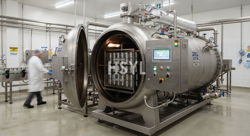
A retort sterilizer is the capital-intensive heart of any thermal canning operation. It determines whether your canned products achieve commercially sterile shelf stability, whether they pass microbiological validation testing for target export markets, whether your per-unit energy cost remains competitive against larger producers, and whether your plant can scale output during seasonal raw material surges without adding a second sterilization line. Selecting the wrong retort means either insufficient lethality delivery requiring product reprocessing or destruction, excessive cycle times that limit daily throughput below break-even volume, or energy consumption that inflates unit cost beyond market-acceptable margins.
This guide covers the three interconnected specification domains that govern retort selection and sizing for canned food applications — batch versus continuous architecture, basket loading and container handling design, and thermal process development including F0 calculation and validation methodology. The framework applies to low-acid canned foods (fish, meat, poultry, vegetable, sauce-based products) where botulism prevention mandates validated sterilization cycles, as well as acidified products where shorter cycles at lower temperatures achieve commercial sterility through pH-dependent pathogen control.
1. Batch Versus Continuous Retort Architecture: When Each Makes Sense
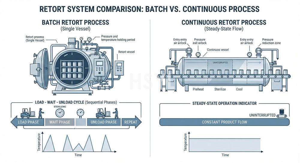
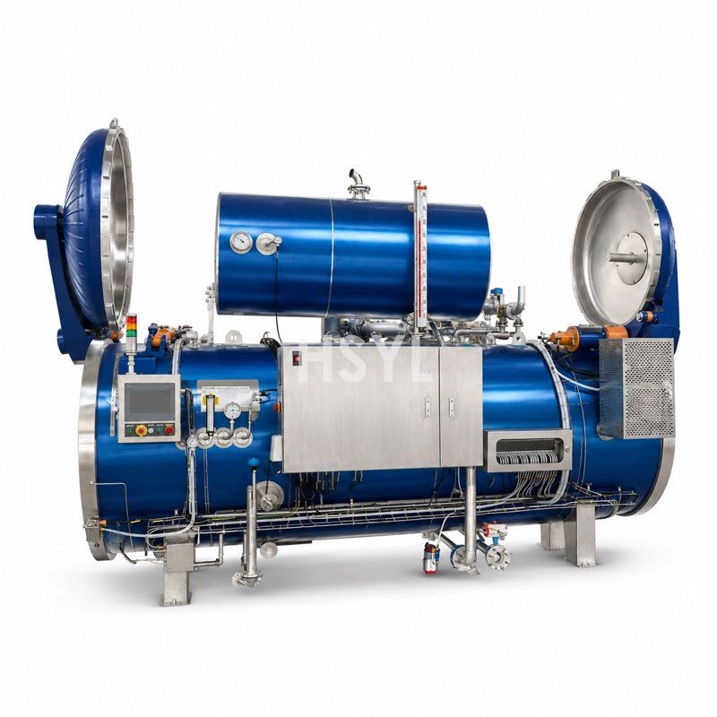
The first architectural decision determines the fundamental operating mode of your sterilization system and constrains every subsequent specification choice. Batch retorts process discrete loads through repeated heat-hold-cool cycles within a single pressurized vessel. Continuous retorts maintain a steady-state thermal zone through which containers move progressively on a carrier system without stopping.
| Factor | Batch Retort System | Continuous Retort System |
|---|---|---|
| Operating Principle | Basket of containers loaded into vessel, door sealed, heating medium introduced to raise chamber temperature to setpoint, held for prescribed duration, cooled, then basket unloaded and next load begins. Cycle repeats continuously throughout shift. | Containers enter one end of long pressurized vessel on continuous carrier (chain, reel, or hydrostatic water columns), progress through pre-heating zone, sterilization holding zone, and cooling zones while vessel remains at process temperature continuously, exit at opposite end fully processed. |
| Typical Capacity Range | 200–4,000 cans per cycle depending on vessel size and can dimensions; 4–20 cycles possible per 24-hour shift yielding 800–60,000 cans daily per vessel | 400–2,000 cans per minute continuous throughput depending on carrier speed and vessel length; 24,000–120,000+ cans daily per line assuming single-shift operation |
| Capital Investment | $80,000–$450,000 per vessel including controls, baskets, and auxiliary systems. Multiple vessels operated in parallel increase total capacity linearly. | $500,000–$3,000,000+ for complete continuous system including carrier mechanism, pressure locks, pre-conditioning chambers, and integrated controls. Cost scales with vessel length and throughput rating. |
| Flexibility Advantage | Each cycle can use independent process parameters. Switching between products, can sizes, or recipe formulations requires only changing the control program and potentially adjusting basket configuration. Single vessel handles unlimited SKU variety without mechanical changeover. | Product changeover requires purging the entire vessel length and re-establishing thermal equilibrium, consuming significant time and energy. Best suited to facilities running limited SKUs in extended production campaigns rather than frequent switching. |
| Labor Requirement | Loading and unloading baskets requires operator attention at cycle boundaries. Automated basket handling systems reduce but do not eliminate this labor component. Labor scales with number of vessels and cycles per shift. | Continuous feeding and discharge require steady operator presence for monitoring but not intermittent heavy lifting. Overall labor per thousand cans processed is significantly lower than batch systems at equivalent throughput. |
| Floor Space | Compact footprint per vessel (typically 3m x 5m to 4m x 8m depending on diameter). Multiple vessels can be arranged in rows sharing utility connections. Suitable for space-constrained facilities. | Elongated footprint following vessel length (typically 15m to 40m). Requires dedicated linear floor area plus clearance for carrier drive mechanism and maintenance access. Not suitable for retrofit into existing buildings without major structural modification. |
Selection Heuristic: If your facility processes more than eight distinct SKUs per week, runs production campaigns shorter than three consecutive days per SKU, or operates in a building where a 20-meter straight-line equipment run is physically impossible, a batch retort system is almost certainly the correct architectural choice regardless of throughput volume. If you produce fewer than four SKUs, each in campaigns exceeding five consecutive days, have available floor space exceeding 300 square meters for sterilization equipment alone, and require sustained output above 80,000 cans per day, a continuous retort merits serious evaluation despite the higher capital commitment.
2. Choose Your Heating Medium: Four Primary Retort Technologies
Within the batch retort category, four distinct heating-medium technologies dominate commercial practice. Each transfers thermal energy to containers through different physical mechanisms, producing different heating-rate characteristics, different uniformity profiles, and different operational constraints that affect product quality, container integrity, and energy consumption.
Water Immersion Retort (Full-Flood)
The oldest and most widely deployed technology. The retort vessel fills completely with overheated water that surrounds all container surfaces during the entire heating phase. Steam injected directly into the water raises temperature to setpoint. Water circulation pumps maintain temperature uniformity throughout the vessel. During cooling, cold water displaces hot water through an overflow system.
- Best for: Glass jars and flexible pouches where even pressure distribution prevents container deformation or breakage. Products sensitive to direct steam contact that might cause surface cooking discoloration or texture damage. Mixed-container loads combining cans, jars, and pouches in the same cycle.
- Heating rate: Moderate to slow due to lower heat transfer coefficient of water compared to pure steam. Come-up time typically 12 to 25 minutes depending on vessel size and initial water temperature.
- Energy profile: Highest water consumption among all technologies because entire water volume heats and cools each cycle. Energy recovery systems (heat exchangers transferring heat from cooling water to incoming process water) reduce net consumption by 30 to 45 percent when properly configured.
- Limitation: Not ideal for rigid metal cans where faster steam-based heating would shorten cycle time and increase daily throughput. Larger vessels experience greater temperature stratification risk requiring careful circulation pump sizing and placement.
Steam-Air Mixture Retort (Overpressure Steam)
A pressurized steam-air blend fills the vessel chamber. A high-velocity circulation fan continuously mixes steam and air to prevent temperature layering while maintaining overpressure above saturation conditions. The air fraction provides the overpressure cushion needed for flexible packaging without submerging containers in liquid.
- Best for: Rigid metal cans requiring fast heating rates combined with moderate overpressure protection for deformed or marginally out-of-spec containers. Semi-rigid plastic trays and bowls where some structural rigidity exists but external pressure support prevents distortion. Operations prioritizing short cycle times over maximum flexibility.
- Heating rate: Fast. Steam delivers latent heat directly to container surfaces. Come-up time typically 8 to 15 minutes for standard can sizes. Fan-assisted mixing eliminates cold spots that plague static steam retorts.
- Energy profile: Lower water consumption than full-immersion systems because no large water volume requires heating and cooling each cycle. Higher steam consumption during heating phase offset by reduced overall cycle time. Net energy per can often 15 to 25 percent better than water immersion for equivalent products.
- Limitation: Fan motor reliability becomes a critical failure point — fan failure during process causes immediate non-uniformity and potential process deviation requiring batch hold-and-evaluate disposition. Not suitable for glass jars where localized hot spots from uneven mixing create thermal stress fracture risk.
Water Spray Retort (Rain-Type)
Spray nozzles mounted above the basket array distribute fine water droplets across the container surfaces while steam injection maintains chamber temperature. The combination of convective heat transfer from droplet impingement and conductive transfer from accumulated thin water film provides rapid, uniform heating without full submersion.
- Best for: High-value products where quality retention justifies premium equipment investment. Facilities running both rigid cans and flexible pouches requiring a single universal retort platform. Applications demanding precise process control with minimal temperature deviation across all container positions in the basket.
- Heating rate: Very fast. Droplet impingement creates high local heat transfer coefficients at contact points. Come-up time achievable in 6 to 12 minutes with optimized nozzle configuration. Among the fastest heating rates available in batch retort technology.
- Energy profile: Moderate water consumption (spray flow rates typically 40 to 80 cubic meters per hour during heating phase, much less than full-flood volumes). Heat recovery integration straightforward through plate heat exchangers on recirculation loops.
- Limitation: Nozzle clogging from scale buildup or particulate matter in water supply reduces spray pattern uniformity over time, requiring disciplined water treatment and periodic nozzle inspection. Initial capital cost exceeds both water immersion and steam-air alternatives by 20 to 35 percent for equivalent vessel size.
Rotary Batch Retort
A variant where the entire basket assembly rotates inside the vessel during processing, usually at 4 to 16 revolutions per minute depending on product viscosity. Rotation induces forced convection inside containers, dramatically accelerating heat penetration for viscous or particulate-laden products where static natural convection produces unacceptably slow center-point heating.
- Best for: Conduction-heating products with high viscosity such as canned stews, thick sauces, corn cream-style vegetables, bean preparations with dense matrix structure, and any product where heat penetration rate limits cycle time in static retorts. Also valuable for large-diameter containers (153mm and above) where the distance from container wall to geometric center creates extended static heating times.
- Heating rate improvement: For conduction-heating products, rotation can reduce required process time by 30 to 50 percent compared to identical product in static retort. The reduction comes from eliminating the stagnant thermal boundary layer inside the container and replacing slow natural convection with continuous fluid motion that brings cooler interior material to the heated wall surface repeatedly.
- Energy impact: Shorter cycle times reduce total energy per batch proportionally. However, the rotary drive motor adds continuous electrical load during rotation, and the rotating seal assembly at the vessel shaft represents a maintenance item not present in static designs. Net energy benefit depends on product type and achieved cycle reduction magnitude.
- Limitation: Unsuitable for products where agitation damages structure (whole fruits, delicate fish fillets, layered products), glass containers (impact stress from rotation), or pouches (mechanical abrasion risk). Mechanical complexity increases maintenance frequency and introduces additional failure modes specific to the drive system.
Practical Recommendation for Fish Canning: Most conventional canned fish products — tuna chunks, sardines in oil or brine, mackerel in tomato sauce, salmon portions — are liquid-particulate systems where the surrounding liquid (oil, brine, sauce) provides adequate natural convection during static heating. Standard steam-air mixture retorts deliver satisfactory cycle times without the added complexity and maintenance burden of rotary systems. Reserve rotary retort consideration for exceptionally viscous fish products such as fish paste spreads, minced fish blocks, or fish-based baby foods where the product matrix behaves as a near-solid conductor.
3. Design Your Basket Loading Pattern for Maximum Capacity Utilization
Every inch of unused space inside a retort basket represents lost throughput capacity that you paid for when purchasing the vessel but cannot utilize. Basket loading pattern design is a geometry optimization problem with hard constraints imposed by container dimensions, heat penetration requirements, and physical handling practicalities.
Geometric Constraints
Round cans pack into rectangular basket footprints according to well-defined mathematical relationships. The optimal packing density depends on the ratio of basket width to can diameter:
| Packing Pattern | Arrangement Geometry | Theoretical Maximum Cans per Layer (as % of footprint) | When Optimal |
|---|---|---|---|
| Square Grid (Aligned) | Cans placed in rows and columns with centers aligned horizontally and vertically. Each can touches four neighbors (except edge positions). | 78.5% (pi/4) | When can diameter divides evenly into basket width with negligible remainder. Rarely optimal in practice except specially-sized baskets. |
| Staggered (Honeycomb) | Alternate rows offset by half-can-diameter so each can sits in the valley between two cans in adjacent row. Each can touches six neighbors. | 90.7% | Virtually always superior to square grid for round cans. Default optimal pattern unless special circumstances apply. |
| Mixed-Diameter Nesting | Smaller cans positioned in interstices between larger cans to fill gaps that would otherwise remain empty. | 92–96% (depends on diameter ratio) | When basket carries multiple can sizes simultaneously and diameter ratio between sizes allows geometric nesting. Requires careful layer planning to avoid unstable stacking configurations. |
Capacity Calculation Example: A standard retort basket measuring 800mm x 1100mm internal footprint carrying 100mm-diameter tuna cans achieves the following capacities per layer: square grid yields 88 cans (8 columns x 11 rows), staggered arrangement yields 101 cans (one extra can per alternating row). Over a six-layer basket, the difference is 528 cans versus 606 cans per load — a 14.8 percent capacity increase from changing the loading pattern alone, with zero additional equipment investment. At 10 cycles per day, that difference equals 780 additional cans processed daily from the same vessel.
Layer Spacing and Vertical Stack Height
The number of layers stacked vertically in each basket determines total cans per load but must respect three constraints:
- Heat penetration uniformity: Containers in the center layer of a tall stack experience slower heating than containers near the top and bottom surfaces because they are thermally insulated by adjacent containers on all sides. Process validation must demonstrate that the coldest point in the worst-positioned can (center of center layer) achieves required lethality. Excessive stack height may force extended hold times that negate the capacity gain from additional layers.
- Structural stability: Tall stacks of metal cans under retort temperature and pressure conditions experience container deformation forces. Bottom-layer cans bear the weight of all layers above plus internal pressure differential during heating. If stack height exceeds the buckling strength tolerance of your can specification, bottom-layer containers deform, causing seam stress, stacking instability, and potential seam failures detectable only after cooling and discharge.
- Operator ergonomics: Loading and unloading baskets with more than 8 to 10 layers requires operators to reach above shoulder height or use mechanical assistance. Consider average operator height, lifting posture safety guidelines, and whether automated basket loaders justify their cost at your production volume.
Basket Handling Equipment Integration
Baskets must move from the loading station into the retort vessel and back to the unloading station at the conclusion of each cycle. Three handling approaches exist:
| Handling Method | Description | Speed Impact on Cycle Time | Labor Implication | Capital Add-On Cost |
|---|---|---|---|---|
| Manual Forklift/Basket Truck | Operator drives loaded basket on wheeled cart or forklift attachment to vessel opening, pushes or lifts basket in, reverses for unload. | Adds 4–8 minutes per cycle depending on operator skill and travel distance | One dedicated operator per 2–3 vessels during loading/unloading windows | $2,000–$8,000 for cart/truck hardware |
| Automatic Basket Loader | Programmed shuttle mechanism retrieves loaded basket from staging position, indexes into vessel, deposits basket precisely on internal supports, retracts and closes door automatically. | Adds 1–2 minutes per cycle (mechanized movement faster than manual positioning) | Reduces operator role to monitoring and exception handling; one loader can serve 2–4 vessels sequentially | $25,000–$80,000 depending on payload capacity and automation extent |
| Overhead Gantry Robot | Gantry-mounted robotic arm grips basket from top, lifts vertically, translates to vessel position, lowers basket into place, releases grip. Handles loading and unloading sequences programmatically. | Adds 0.5–1.5 minutes per cycle (fastest option) | Near-zero direct operator involvement for basket movement; operator focuses on upstream filling and downstream labeling stations | $80,000–$200,000 depending on reach, lift capacity, and programming sophistication |
4. Develop Your Thermal Process: F0 Calculation and Validation Fundamentals
Selecting a retort vessel is meaningless without defining the thermal process that the retort will execute. The thermal process specification — expressed primarily as the F0 lethality value — determines required retort temperature, hold time, come-up time allowance, and cooling parameters. These process variables then determine minimum vessel performance specifications and ultimately constrain which retort models qualify for your application.
What Is F0 and Why Does It Matter?
F0 measures the total lethal heat delivered to a food product during thermal processing, expressed as an equivalent number of minutes at 121.1°C (250°F) referenced against the thermal destruction kinetics of Clostridium botulinum spores. An F0 of 3.0 minutes is the internationally accepted minimum lethality requirement for low-acid canned foods (pH above 4.6) to achieve commercial sterility with respect to botulism prevention. Many commercial processes specify F0 values ranging from 4.0 to 12.0 or higher depending on product characteristics, target microorganism of concern, and desired spoilage probability reduction.
The F0 value accumulates throughout the entire thermal process — during come-up time as temperature rises toward setpoint, during the hold period at constant retort temperature, and during the initial portion of cooling before product temperature drops below the lethal threshold. Modern retort control systems calculate and display accumulating F0 in real time during each cycle, allowing operators to verify that target lethality has been achieved before initiating cooldown.
Process Development Steps
- Determine product heat-penetration characteristics. Instrument sample cans with thermocouples positioned at the geometric center (slowest-heating point) of the most challenging product variant — highest viscosity, largest container size, highest solids loading, coldest-fill-temperature condition. Run test processes through the candidate retort to measure actual temperature-over-time profiles at the critical point.
- Calculate F0 from heat-penetration data. Apply the General Method (Bigelow equation integration) or Ball formula method to convert the measured temperature-time curve into cumulative F0. Verify that calculated F0 meets or exceeds the target lethality value with appropriate safety margin (typically 10 to 20 percent above theoretical minimum).
- Identify the worst-case process deviation scenario. Define the combination of initial temperature, fill weight, product consistency, container orientation, and retort position that produces the lowest F0 among all legitimate production variations. Your validated process must deliver adequate lethality even under this worst-case condition.
- Establish critical process factors and operating limits. Document every variable that materially affects delivered F0: retort temperature setpoint and allowable deviation (typically plus or minus 0.5°C), hold time minimum, initial product temperature minimum, come-up time maximum, cooling parameters. These become the control limits programmed into the retort PLC and monitored during every production cycle.
- Conduct heat distribution study within the retort vessel. Place temperature sensors at multiple locations throughout an empty or water-loaded vessel (or preferably a fully loaded basket array) during a representative process cycle. Verify that temperature variation across all sensor positions stays within acceptable limits (typically plus or minus 0.5 to 1.0°C from setpoint during hold period). Locations consistently reading colder than others represent cold spots that may cause under-processing if product routinely occupies those positions.
- Submit documentation for regulatory filing or third-party process authority review. Depending on your target market, thermal process records require approval from recognized process authorities (Institute for Thermal Processing Specialists, university extension programs, or government food safety agencies) before commercial production commences. Documentation includes heat penetration data, heat distribution data, F0 calculations, process specifications, and deviation handling procedures.
Validation Timeline Reality: Complete thermal process development from initial instrumentation trials through final authority approval typically requires 8 to 16 weeks for a single product-container combination in a newly installed retort. If your product portfolio includes multiple container sizes, multiple recipes, or multiple retort vessels, plan for parallel development streams and budget for process authority fees ($3,000–$15,000 per product-process combination depending on complexity and jurisdiction).
5. Size Your Retort Capacity: Matching Vessel Specification to Production Demand
With architecture, heating method, loading pattern, and thermal process defined, the final sizing exercise matches vessel dimensions, cycle time, and quantity to your production demand profile. Undersizing leaves money on the table during peak season. Oversizing ties up capital in idle capacity and increases fixed-cost burden per unit during off-peak periods.
Stepwise Sizing Calculation
Step A: Define daily production target in cans. Start from your contracted or forecast sales volume converted to daily can output. Include buffer for anticipated growth (15–25 percent over current year) and account for yield loss (typically 1–3 percent rejection at retort discharge visual inspection plus downstream losses).
Step B: Determine effective process cycle time. Sum the component durations: come-up time (heat-up from loading completion to setpoint attainment), hold time (prescribed by your validated process), and cooling time (from start of cool-down to vessel depressurization and safe door-opening temperature). Add basket load/unload handling time (manual or automated). Add a 5–10 percent contingency for minor delays and instrument verification pauses. This total equals your effective cycle time per batch.
Step C: Calculate cans per batch from basket configuration. Multiply cans per layer by number of layers per basket by number of baskets per vessel load. Verify this figure against your loading pattern design work from Section 3.
Step D: Compute batches per shift and vessels required. Divide daily target (Step A) by cans per batch (Step C) to get required batches per day. Multiply cycle time (Step B) by batches required to get total vessel-minutes needed. Divide by available production minutes per day (shift hours minus breaks, cleaning windows, and planned maintenance) to determine how many vessels operating in parallel satisfy the demand. Round up to whole vessels — partial vessels do not exist.
| Example Scenario | Tuna Cannery (Standard Product) | Sardine Cannery (Smaller Cans) |
|---|---|---|
| Daily production target | 52,000 cans (170g net, D100 cans) | 85,000 cans (120g net, D73 cans) |
| Effective cycle time | 65 minutes (12 min CUT + 45 min hold + 8 min cool + handling) | 55 minutes (10 min CUT + 35 min hold + 8 min cool + handling) |
| Cans per basket (6-layer staggered) | 606 cans/basket x 2 baskets/vessel = 1,212 cans/load | 980 cans/basket x 3 baskets/vessel = 2,940 cans/load |
| Batches required daily | 43 batches (52,000 / 1,212) | 29 batches (85,000 / 2,940) |
| Vessel-minutes needed | 2,795 min (43 x 65) | 1,595 min (29 x 55) |
| Available minutes (double shift) | ~900 minutes | ~900 minutes |
| Vessels required | 3.1 → 4 vessels (operating staggered cycles) | 1.77 → 2 vessels |
Staggered Multi-Vessel Operation
When your calculation indicates a fractional vessel requirement between 1 and 2, staggered multi-vessel operation allows you to approach continuous-like throughput from batch equipment. Instead of loading all vessels simultaneously and waiting for all to complete before reloading, stagger vessel start times so that one vessel completes its cycle approximately every (cycle time divided by vessel count) minutes, creating a quasi-continuous stream of processed batches exiting to the unloading station.
In the tuna example above, four vessels with 65-minute cycles staggered at 16-minute intervals (65 / 4 ≈ 16) produce one completed batch every 16 minutes on average, delivering 90 batches per 24-hour period (1,440 / 16) and exceeding the 43-batch requirement with substantial capacity margin for peak-demand days. The trade-off is that staggered operation requires coordinated scheduling discipline — if one vessel falls behind schedule due to a minor fault or delayed basket availability, the ripple effect propagates through subsequent vessel starts unless the schedule dynamically adjusts.
6. Utility Requirements and Facility Preparation
Retort sterilizers impose substantial demands on facility utilities that must be engineered before equipment installation proceeds. Underestimating utility requirements is among the most common causes of commissioning delays and post-installation performance shortfall.
| Utility | Requirement Basis | Typical Range for Mid-Size Batch Retort (D1200 x L2400 mm) | Facility Preparation Notes |
|---|---|---|---|
| Steam Supply | Heating phase consumption peaks during come-up time. Steam quality must be dry saturated (minimum 95% dryness fraction) at pressure sufficient to achieve retort setpoint plus piping loss margin. | 800–2,500 kg/h peak demand during come-up; 200–600 kg/h average during hold | Dedicated steam header from boiler to retort battery recommended. Pressure-reducing valve station at retort location. Steam traps on all supply and condensate return lines. Insulation on all exposed piping to prevent condensation dripping and personnel burn hazard. |
| Cooling Water | Cooling phase consumes large volume to remove sensible heat from vessel shell, basket mass, and product contents. Temperature rise across the retort (outlet minus inlet) determines flow rate required. | 15–50 m³/h during active cooling phase lasting 15–30 minutes per cycle | Cooling tower or chiller capacity must accommodate simultaneous cooling demand from all vessels operating staggered cycles. Water quality (hardness, chloride content, microbial load) affects nozzle performance and internal corrosion rates. Consider heat recovery from hot effluent to preheat incoming make-up water. |
| Compressed Air | Overpressure control during heating and cooling phases. Pneumatic actuation for valves, door mechanisms, and basket-handling equipment. Control system air consumption. | 0.5–2.0 Nm³/min at 6–7 bar (depending on automation level) | Dry, oil-free compressed air preferred to avoid contaminating food-contact areas or fouling pneumatic components. Air dryer and filtration package required if plant compressed air supply does not meet food-grade quality standards. |
| Electrical Power | Control system, circulation pump motors, fan motors (steam-air retorts), drive motors (rotary retorts), lighting, instrumentation. | 5–25 kW connected load depending on retort type and auxiliary equipment | Three-phase power recommended for motors above 3 kW. Voltage stability within plus or minus 5 percent essential for PLC and precision control components. Uninterruptible power supply or controlled shutdown sequence required to prevent mid-cycle abort scenarios during power interruption. |
| Drainage | Cooling water effluent, vessel blowdown, cleaning solution discharge, floor washdown runoff. Effluent temperature may exceed environmental discharge limits requiring tempering. | Peak flow matching cooling water inlet rate during cooling phase | Floor drainage around vessel base graded to prevent pooling. Effluent collection pit with temperature monitoring if local regulations restrict thermal discharge. Connection to facility wastewater treatment system sized for peak surge flows during simultaneous vessel cooling events. |
7. Common Mistakes in Retort Selection That Cause Expensive Problems Later
- Specifying retort temperature based on competitor claims rather than your actual product heat penetration data. A competitor advertising 115°C processing for a similar-sounding product does not mean your product formulation will achieve adequate lethality at that temperature. Viscosity differences, particle size distribution, headspace volume, fill weight variation, and container wall thickness all affect heat penetration rate independently of nominal product category. Run your own heat penetration tests before committing to any temperature specification, and validate the resulting F0 calculation through an accredited process authority.
- Ignoring come-up time when comparing quoted cycle times between suppliers. Some suppliers quote only the hold time when marketing cycle performance, omitting come-up time and cooling time from their published figures. A retort with a 35-minute hold time but 18-minute come-up time delivers slower throughput than a competing model with 42-minute hold time but 10-minute come-up time when total cycle time determines daily batch count. Always request total-cycle-time breakdown including all phases before evaluating comparative performance claims.
- Selecting vessel diameter based on basket footprint alone without verifying heat distribution adequacy. Large-diameter vessels offer attractive per-basket capacity but present increasing challenges for maintaining temperature uniformity across the full cross-section during the hold period. A vessel that passes heat distribution tests with empty baskets or water-load simulation may develop unacceptable cold-spot patterns when fully loaded with actual product, especially if circulation pump capacity was specified for the easier test condition. Require heat distribution validation under worst-case fully-loaded production configuration before accepting final delivery.
- Underestimating the impact of scheduled and unscheduled downtime on effective throughput. Capital cost comparisons frequently assume 95 percent or higher equipment availability. Real-world retort operations achieving 85 percent OEE are considered well-managed. The gap between theoretical and actual availability comes from scheduled preventive maintenance (descaling, seal inspection, sensor calibration), unscheduled repairs (valve failures, sensor drift, door seal degradation), and operational delays (basket unavailability, operator absence, upstream filler stoppages feeding the retort). Build your business case on conservative availability assumptions (80–85 percent initially, improving to 87–92 percent after the first year of operational learning).
- Purchasing a retort without confirming process authority acceptance of the proposed control system and data logging capability. Regulatory bodies and process authorities increasingly require electronic records demonstrating that every can produced received its validated process with no deviation from specified parameters. A retort with basic temperature indication but inadequate data logging resolution, missing audit trail functionality, or incompatible file formats for authority submission may be technically functional but legally non-compliant for products destined to regulated markets. Verify data logging specifications against authority requirements before purchase, not after installation when retrofitting becomes expensive or impossible.
- Neglecting future expansion provisions during initial facility layout. Adding a second or third retort vessel later requires steam header capacity expansion, cooling water infrastructure upgrade, electrical panel modification, floor space allocation that may no longer be available, and control system integration that may be incompatible with original equipment generation. Specifying the initial installation with explicit utility provisioning for planned future vessels (oversized steam main with capped stubs, spare cooling tower cell capacity, electrical panel with reserved breaker spaces, concrete foundation reinforcement for additional vessel mounting pads) costs marginally more during construction but saves multiples of that amount when expansion actually occurs.
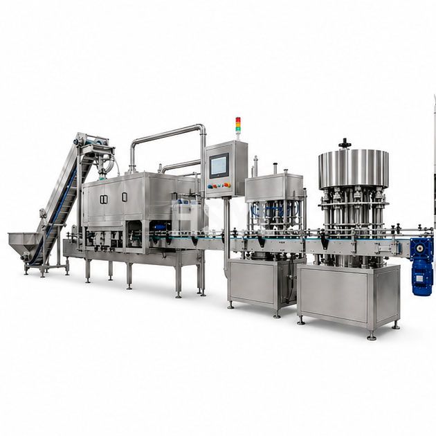
8. How Retort Selection Connects to Upstream and Downstream Equipment
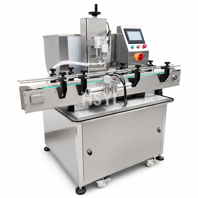
Your retort sits between the seamer (which delivers sealed containers to the retort loading station) and the downstream labeling, case-packing, and warehousing operations (which receive thermally processed containers from the retort discharge station). Interface compatibility at both boundaries affects total line performance as much as the retort's own specifications.
The seamer-to-retort interface determines the condition of containers entering the sterilization cycle. Seam quality from the seamer directly influences retort safety — marginal seams that hold vacuum at ambient temperature may fail under the combined internal pressure buildup and external handling stress of retort processing, causing contamination events that affect entire retort batches rather than individual defective units. This is why inline seam monitoring and rejection capability on the seamer is non-negotiable for retort-fed operations, and why the retort selection process should include a joint review of seam quality standards with your seamer supplier to ensure the combined system delivers containers capable of surviving retort conditions without failure.
The retort-to-labeling interface determines the information flow and handling compatibility between sterilization completion and finished-goods dispatch. Retort discharge temperature affects label adhesive performance (some adhesives fail above certain surface temperatures), ink stability (thermal-sensitive inks may discolor), and case-packaging timing (hot containers condense moisture inside cases causing cardboard degradation). If your retort discharges containers above 50°C surface temperature, intermediate cooling conveyors or forced-air cooling tunnels may be necessary before containers reach labeling stations — an interface element frequently overlooked during retort specification but discovered during commissioning when label adhesion problems emerge unexpectedly.
Integrated Line Perspective: HSYL provides coordinated equipment solutions spanning the complete canning workflow from preparation through sterilization to packaging. Review the commercial kitchen and food processing solutions overview for integrated line configuration guidance that addresses retort interfacing with upstream sealing equipment and downstream handling systems as a unified design rather than isolated equipment selections.
Related Equipment for Thermal Processing Lines
Retort sterilizers operate within a broader ecosystem of food processing equipment. The following categories interact directly with retort selection, sizing, and operation:
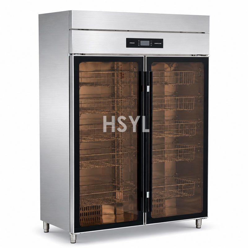
- Automatic Steamer Cabinets — Pre-cooking and blanching equipment for raw ingredients before canning. Pre-cooking parameters (temperature, hold time, product texture after steaming) influence initial product temperature entering the retort and the resulting heat penetration behavior during sterilization. Consistent pre-cooking reduces retort process variability between batches.
- Gas Steamer Cabinets — Alternative heating source for pre-processing operations in facilities where electrical supply capacity is constrained but gas infrastructure is available. Gas-powered steam generation decouples pre-processing energy demand from the electrical load that retort vessels themselves impose during peak processing periods.
- How to Choose Commercial Kitchen Equipment for Central Kitchens — Planning methodology applicable to central food processing facilities including canning plants. Covers capacity calculation frameworks, layout zoning principles, utility sizing approaches, and vendor evaluation criteria that parallel the retort-specific considerations detailed in this guide.
- Food Factory Engineering Layout and Cost Guide — Facility-level resource for designing or expanding food processing floors around new retort installations. Addresses floor loading (retort vessels weigh 2–8 tonnes filled), seismic anchoring requirements, utility routing coordination, service access clearance for maintenance, and expansion provision strategies mentioned in Section 7.
Frequently Asked Questions
What is the difference between batch retort and continuous retort for canned food?
What is F0 value in retort sterilization?
Which retort heating method is best for canned fish products?
How do you calculate how many retort vessels you need for your canning line?
What is the difference between water immersion retort and steam-air retort?
How long does a typical canned fish retort cycle take?
What basket loading pattern gives the most cans per retort load?
What utility infrastructure does a retort sterilizer need?
Related Articles


Get professional consultation
Do you have any questions or need technical support regarding the content of this article? Fill out the form below, and our expert team will provide you with professional solutions.