Most commercial kitchen layout problems trace back to a single planning failure: treating equipment placement as a space-fitting exercise rather than a workflow and hygiene zoning problem. When a kitchen is planned by drawing equipment footprints on a floor plan until everything fits, the result looks efficient on paper but produces cross-contamination risks, heat migration into cold storage, operator congestion during peak service, and ventilation systems that cannot keep up with the actual cooking load. The correct approach reverses the sequence: define the zones first, then place equipment within them, then verify that ingredient flow, exhaust capacity, and drainage support the resulting layout.
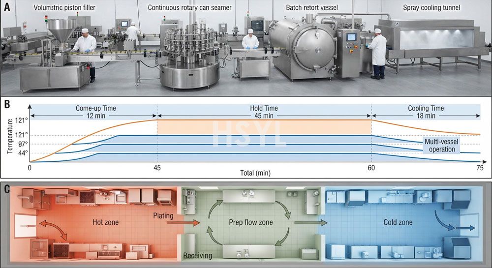
This guide walks through a three-zone layout planning framework built around hot zone, cold zone, and prep flow separation. The framework applies to standalone restaurants producing 80 to 400 meals per service, central kitchens supplying multiple outlets with 1,000 to 10,000 meals per day, hotel kitchen complexes supporting banquet and all-day dining simultaneously, and institutional kitchens in schools, hospitals, and corporate cafeterias. For an integrated view of how individual equipment categories fit into a complete kitchen workflow, see HSYL's commercial kitchen equipment solutions overview.
The planning methodology does not require CAD software or specialized consulting — it requires a scaled floor plan, an equipment list with utility requirements, and the discipline to separate zones before placing any single piece of equipment. The three-zone framework is not the only valid layout approach, but it is the most reliable starting point for kitchens where food safety, operational efficiency, and staff safety all matter simultaneously.
1. Why Three-Zone Separation Is the Foundation of Kitchen Layout
Commercial kitchen layout is governed by three physical realities that cannot be negotiated away: heat migrates from hot equipment into adjacent spaces and must be contained, cold storage loses efficiency when exposed to heat or air movement from other zones, and raw ingredients carry contamination risk that must be contained within defined prep paths before reaching cooked or plated food. A layout that ignores any of these realities creates operational problems that no amount of equipment quality or staff training can overcome.
The three-zone framework addresses these realities directly:
| Zone | Primary Function | Dominant Physical Concern | Layout Implication |
|---|---|---|---|
| Hot Zone | Cooking, frying, baking, steaming, holding | Heat generation, grease-laden exhaust, combustion air for gas equipment | Position under dedicated exhaust hoods with makeup air supply; isolate from cold storage and raw prep to prevent heat migration and condensation |
| Cold Zone | Refrigerated storage, frozen storage, ice production, chilled prep | Heat infiltration from adjacent zones, condensate drainage, compressor airflow | Position against exterior walls where possible; maintain clearance from hot zone and cooking exhaust; provide floor drain for condensate |
| Prep Flow Zone | Ingredient receiving, washing, cutting, marinating, assembly, plating | Cross-contamination between raw protein types and between raw and ready-to-eat food | Position between cold zone (ingredient source) and hot zone (cooking destination); separate raw protein prep from vegetable prep from plating by distance or physical barrier |
Zoning Discipline: The three zones are defined by their dominant physical concern, not by the equipment they contain. A prep table used for cold salad assembly is functionally part of the cold zone even if it sits at room temperature, because its contamination risk profile matches cold-zone logic. A holding warmer next to the plating station is functionally part of the hot zone even if it produces minimal heat, because its placement affects exhaust and airflow. Classify each station by its physical concern before placing it on the floor plan.
2. Hot Zone Planning: Equipment Placement, Exhaust and Makeup Air
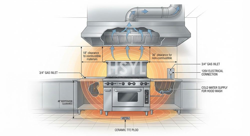
The hot zone is the most utility-intensive area of any commercial kitchen. Gas cooking equipment requires combustion air at rates specified by local gas code, typically 1 square inch of free opening per 2,000 BTU per hour of input. Electric cooking equipment avoids combustion air requirements but imposes peak electrical demand that may require dedicated circuit capacity beyond what the facility currently supports. Both fuel types generate heat, grease-laden vapor, and moisture that the exhaust system must remove continuously during operation.
Exhaust Hood Coverage and Capture Velocity
Every piece of cooking equipment that produces grease-laden vapor — fryers, griddles, charbroilers, wok ranges, tilting skillets, and combination ovens — must sit under a Type I exhaust hood with grease removal filters. The hood must overhang the cooking surface by a minimum of 6 inches on all open sides, and the duct capture velocity at the filter face must achieve 400 to 500 feet per minute for medium-duty cooking and 500 to 700 feet per minute for heavy-duty charbroiling or wok cooking. Undersized hoods allow grease vapor to escape into the kitchen, creating fire risk on surrounding surfaces and odor migration into dining areas.
Hot Zone Equipment Arrangement
Within the hot zone, equipment arrangement follows a heat-progression principle: the highest-heat equipment (charbroilers, wok ranges, fryers) occupies the center of the cooking line under the highest-capacity hood section, while lower-heat equipment (steamers, holding cabinets, ovens) occupies the perimeter. This concentrates the heaviest exhaust load where capture velocity is highest and prevents heat from radiating into adjacent low-heat stations where operators work for extended periods.
For a typical full-service restaurant hot zone, a multi-burner cooking range such as the Cooking Range 700 Series provides the modular foundation for the cooking line, with fryer, griddle, and pasta cooker modules added as menu requirements dictate. The 700mm depth matches standard hood coverage and allows operators to reach across the range without exceeding ergonomic reach distance. Position the range with a minimum of 3 feet of clear aisle behind the operator for safe movement during peak service.
Makeup Air and Combustion Air
Exhaust hood systems remove 1,000 to 5,000 cubic feet per minute of air from the hot zone depending on hood size and cooking load. This air must be replaced by makeup air at a rate approximately equal to the exhaust rate, minus a small negative pressure differential of 0.02 to 0.05 inches of water gauge. Without adequate makeup air, the kitchen develops negative pressure that pulls conditioned air from dining areas through doorways, creates draft issues at exterior doors, and can cause gas equipment backdrafting that introduces combustion products into the kitchen. Plan makeup air supply ductwork in the same planning phase as exhaust ductwork — retrofitting makeup air into an existing kitchen is substantially more expensive than including it in the initial build.
3. Cold Zone Planning: Refrigeration, Ice Production and Condensate Management
The cold zone serves two functions: bulk storage of refrigerated and frozen ingredients, and production of ice used for ingredient cooling, beverage service, and display. Both functions depend on equipment that rejects heat through condenser coils into the surrounding air, which means the cold zone is paradoxically a net heat producer at the room level. Positioning the cold zone adjacent to the hot zone creates a mutual efficiency penalty: refrigeration condensers draw heated air from the hot zone and must work harder to reject their own heat, while hot zone exhaust systems pull cooled air from the cold zone and waste refrigeration capacity.
Walk-In Cooler and Freezer Placement
Walk-in coolers and freezers occupy the largest equipment footprint in the cold zone and determine its overall position within the kitchen. Three placement principles govern walk-in location:
- Position against exterior walls when possible: Exterior wall placement allows condenser heat rejection directly outside the kitchen, eliminating the internal heat load from condenser operation. This is particularly important for walk-in freezers, whose condensers run longer cycles and reject more heat than cooler condensers.
- Maintain minimum 4-inch clearance on all non-wall sides: Condenser airflow requires unobstructed intake and discharge paths. Insufficient clearance causes condenser cycling, temperature instability, and premature compressor failure. The 4-inch minimum assumes a remote condenser; self-contained units with integrated condensers require 12 to 24 inches of clearance on the condenser discharge side.
- Orient doors to prevent cold air spillage into hot zone: Walk-in doors open to release cold air; if the door faces the hot zone, the released cold air immediately mixes with hot kitchen air and creates condensation on floors, walls, and adjacent equipment. Orient doors toward the prep zone or receiving area where ambient temperature is lower and air movement is minimal.
Ice Machine Placement
Ice machines are the most frequently mispositioned equipment in commercial kitchen cold zones. Operators often place ice machines in bar areas or remote service stations for convenience, but ice machines are heat-producing refrigeration equipment that also requires substantial water supply and floor drainage for condensate and cycle purge water. Position ice machines within the cold zone utility cluster, close to the walk-in cooler but with the required condenser clearance. A flake ice machine such as the Flake Ice Machine-AP Series produces ice suitable for ingredient display, seafood chilling, and bakery dough temperature control — applications that place it in the prep-to-cold zone boundary rather than in beverage service areas.
Condensate Drainage
Every piece of refrigeration equipment produces condensate — water that condenses on cold evaporator coils and must drain to a sanitary waste connection. Condensate drainage is the most frequently overlooked utility in cold zone planning. Each evaporator requires a dedicated drain line with a minimum 1-inch diameter, a P-trap to prevent sewer gas backup, and an air gap at the drain connection to prevent cross-contamination between the drain system and the food-safe equipment. Floor drains in the cold zone must be positioned to capture both condensate and cleaning water, with floor slope of 1/4 inch per foot directed toward the drain. Without adequate floor slope, condensate and cleaning water pool around equipment bases, creating slip hazards and microbial growth conditions.
4. Prep Flow Planning: Ingredient Movement and Cross-Contamination Prevention
Prep flow is the connective tissue between cold zone (where ingredients are stored) and hot zone (where ingredients are cooked). A well-designed prep flow moves ingredients from receiving through cold storage to prep stations to cooking equipment to plating without raw and ready-to-eat ingredients crossing paths. Cross-contamination — the transfer of pathogenic microorganisms from raw food to ready-to-eat food — is the single largest food safety risk in commercial kitchens, and layout planning is the most effective control measure because it eliminates the risk structurally rather than relying on operator behavior.
One-Directional Ingredient Flow Principle
Ingredient movement through the kitchen should follow a one-directional path from raw receiving to finished plate, without backtracking. The canonical flow is: Receiving dock to cold storage to prep stations to cooking equipment to plating station to service pass. Any layout that requires ingredients to move backward through this path — for example, carrying prepped vegetables from a prep station past the cooking line to reach a holding cabinet on the far side — creates congestion, contamination risk, and efficiency loss.
| Flow Stage | Position in Kitchen | Adjacent Zone | Cross-Contamination Control |
|---|---|---|---|
| Receiving | Receiving dock or pass-through entry, isolated from main kitchen | Cold zone (direct access to cold storage) | Inspect and accept raw ingredients before they enter cold storage; reject damaged or temperature-abused deliveries at the dock |
| Cold Storage | Cold zone, between receiving and prep | Receiving on one side, prep on the other | Store raw proteins on lower shelves, ready-to-eat foods on upper shelves; maintain 40 degrees Fahrenheit or below |
| Raw Protein Prep | Dedicated prep station separated from vegetable prep by minimum 5 feet or physical divider | Cold zone (ingredient source) | Dedicated cutting boards, knives, and containers color-coded by protein type (red for meat, blue for seafood, yellow for poultry); never share equipment between protein types without full washing and sanitizing |
| Vegetable and Ready-to-Eat Prep | Separate prep station on the cooked-food side of the kitchen, away from raw protein prep | Hot zone (cooked food source) and plating | Green-coded equipment; never handle raw proteins at this station; wash and sanitize between batches |
| Plating and Service | Between cooking equipment and service pass, on the cooked-food side | Hot zone (cooked food source) | Clean hands and sanitized tools only; no raw ingredient contact at plating station |
Handwashing Station Placement
Handwashing stations are the operational backstop for cross-contamination prevention, but they only function if operators can reach them quickly and without crossing contamination zones. Place dedicated handwashing sinks at three locations: at the transition from receiving to cold storage, at the transition from raw protein prep to cooking, and at the plating station. Each handwashing sink must be dedicated to handwashing only (not food preparation or equipment washing), supplied with hot and cold water, soap, and single-use towels, and positioned so the operator does not need to touch a door handle or contaminated surface between washing and resuming work.
Hygiene Zone Boundary Equipment
Kitchens that serve high-risk populations — hospitals, nursing homes, schools, and central kitchens supplying multiple outlets — often require a dedicated hygiene zone boundary between raw and clean areas. Pass-through sterilizer chambers installed in the wall between raw prep and clean prep areas allow containers, utensils, and packaged ingredients to move from raw to clean side through a validated sterilization cycle, eliminating the risk of manual cross-contamination during transfer. The Double Door Sterilizer Pass-Through Chamber provides this function with interlocked doors that prevent both doors from opening simultaneously, maintaining the physical separation between raw and clean zones at all times. For lower-risk operations, a dedicated pass-through window with handwashing sink at the transition point may suffice.
5. Utility and Drainage Planning Across All Three Zones
Utility planning — water supply, drainage, gas, electrical, and ventilation — must be coordinated with zone planning rather than treated as a separate engineering exercise. The most common layout failure is designing a zone arrangement that looks correct on a floor plan, then discovering during construction that the required utility connections cannot be routed to the equipment locations without major structural modification.
Water Supply and Drainage
Hot water supply must reach every prep sink, handwashing sink, and equipment sink at a minimum of 120 degrees Fahrenheit for grease removal effectiveness. Cold water supply serves ice machines, food prep sinks, and pot fillers. Drainage capacity must handle simultaneous peak flow from all connected fixtures — a single 4-inch floor drain typically handles 20 to 30 gallons per minute, which is sufficient for one prep sink plus one ice machine plus floor washdown, but may be insufficient for a combi oven dump drain or a steamer condensate drain added to the same branch. Plan floor drain locations at the lowest point of each zone, with floor slope of 1/4 inch per foot directed toward the drain. Do not route floor drains under equipment — a clogged drain under a cooking range cannot be accessed without moving the equipment.
Gas and Electrical
Gas piping requires dedicated shut-off valve access within 6 feet of each gas appliance, with flexible gas connector length limited to 6 feet per most local codes. Gas piping must be routed along walls or ceiling, never through or under floor slabs where leaks cannot be detected. Electrical service to cooking equipment requires dedicated circuits sized to the equipment nameplate rating multiplied by 125 percent for continuous loads. Plan electrical panel location within line-of-sight of the cooking equipment disconnect means — an electrical panel in a separate room requires a labeled disconnect switch within sight of the equipment, adding cost and complexity.
Ventilation Balance
The total kitchen ventilation system must balance exhaust air removal with makeup air supply to maintain a slight negative pressure of 0.02 to 0.05 inches water gauge relative to adjacent dining and corridor areas. Excessive negative pressure pulls dining area conditioned air into the kitchen through doorways, creating comfort and energy problems. Insufficient negative pressure allows kitchen odors to escape into dining areas. Balance is achieved by sizing makeup air supply at approximately 90 to 95 percent of exhaust rate, with the remaining 5 to 10 percent made up by infiltration through doorways and transfer grilles from adjacent conditioned spaces. Test and balance the system after installation — specified airflow rates rarely match actual performance without field adjustment.
6. Common Layout Mistakes and How to Avoid Them
- Placing the cooking line in the center of the kitchen to create a showpiece island. Center-island cooking lines look impressive in architectural renderings but require exhaust ductwork routed through the ceiling above, makeup air distributed from multiple directions, and gas and electrical services trenched through the floor slab. They also create heat radiation on all four sides, requiring operators to work in a heat envelope rather than against a cooler wall. Position cooking lines against an exterior wall where exhaust ductwork can route directly up and out without horizontal runs that accumulate grease.
- Putting the walk-in cooler door facing the cooking line for easy ingredient access. This is the most common cold zone planning error. Every time the walk-in door opens, cold air spills onto the kitchen floor and immediately contacts hot cooking equipment, creating condensation on equipment surfaces, slip hazards on floors, and substantial refrigeration efficiency loss. Orient walk-in doors toward the prep zone or receiving area, even if this requires a longer walking path for cooks retrieving ingredients.
- Combining raw protein prep and vegetable prep at the same workstation to save space. Cross-contamination between raw chicken and ready-to-eat vegetables is a leading cause of foodborne illness outbreaks in commercial kitchens. The 5-foot minimum separation between raw protein prep and vegetable prep is not a suggestion — it is the operational distance required for an operator to wash hands and change cutting boards between handling raw and ready-to-eat foods without contamination. If space constraints prevent 5-foot separation, install a physical divider (sneeze guard or partition) between the stations.
- Undersizing floor drains to save on plumbing costs. Floor drain capacity is a capital expense that pays back over the life of the kitchen. Undersized drains clog during peak cleaning operations, causing water backup that contaminates food contact surfaces and forces kitchen shutdown. Plan one 4-inch floor drain per 200 square feet of kitchen floor area, with additional drains at each ice machine, combi oven, and steamer location.
- Relying on a single exhaust hood for the entire cooking line without calculating per-equipment capture velocity. A hood that covers the entire cooking line looks sufficient but may lack the capture velocity to handle the heaviest grease-producing equipment (charbroiler, fryer) positioned at one end. Calculate required CFM for each piece of equipment under the hood, sum the requirements, and verify that the hood's rated capacity exceeds the total by at least 15 percent for safety margin.
- Omitting handwashing sinks from the initial floor plan to save space, then adding them as an afterthought. Handwashing sinks are non-negotiable food safety equipment, not optional accessories. A kitchen layout without dedicated handwashing stations at zone transitions will fail health department inspection and create operational contamination risks that no amount of training can overcome. Plan handwashing sink locations in the same planning phase as cooking and refrigeration equipment.
- Positioning ice machines in bar or beverage areas far from the cold zone utility cluster. Remote ice machines require dedicated water supply lines, floor drains, and electrical service routed to locations that may not have existing utility infrastructure. The installation cost premium for remote ice machine placement often exceeds the cost of repositioning beverage service closer to the cold zone. Consolidate ice production in the cold zone and transport ice to point of use in insulated containers.
7. The Cost-Value Logic of Proper Layout Planning
Proper layout planning costs money during the planning phase — scaled drawings, equipment specification coordination, and mechanical engineering review all add to pre-construction expense. But the cost of poor layout planning compounds over the life of the kitchen in ways that dwarf the upfront planning investment.
| Layout Problem | Planning Cost to Avoid | Operational Cost If Not Avoided | Typical Payback Period |
|---|---|---|---|
| Inadequate exhaust hood capacity | Hood sizing calculation and mechanical engineering review: $500 to $2,000 | Kitchen odor migration into dining, grease accumulation on surfaces, fire inspection failure, hood fire risk: $5,000 to $50,000 per incident | 3 to 12 months |
| Walk-in door facing hot zone | Floor plan revision to reorient door: minimal design cost | Refrigeration efficiency loss 15 to 25 percent, equipment runtime increase, compressor service life reduction: $200 to $800 per month in energy and maintenance | 1 to 3 months |
| Combined raw and ready-to-eat prep | Additional 5 feet of counter space and second cutting board set: $300 to $1,000 | Foodborne illness outbreak risk, health department violation, potential kitchen closure: $10,000 to $500,000 per incident | Immediate (risk avoidance) |
| Undersized floor drains | Additional drain installation: $500 to $2,000 per drain | Floor water backup, food contamination, kitchen shutdown during service: $2,000 to $10,000 per shutdown event | 3 to 24 months |
| Negative pressure imbalance | Test and balance after installation: $800 to $3,000 | Dining area discomfort, conditioned air loss, gas equipment backdrafting risk: $200 to $1,000 per month in energy and comfort complaints | 3 to 18 months |
Investment Priority: If budget constraints force prioritization, invest first in exhaust hood sizing and makeup air balance — these are the most expensive systems to retrofit after construction. Invest second in floor drain capacity and placement — drains cannot be added without breaking the floor slab. Invest third in walk-in cooler orientation and door placement — reorienting a walk-in after installation requires substantial construction work. Invest fourth in prep station separation — this can be improved with dividers and equipment rearrangement if initial layout is suboptimal. The pattern is clear: invest in things that are impossible or expensive to change after construction, and accept compromises on things that can be revised later.
8. Layout Verification Before Construction
Before finalizing a kitchen layout for construction, verify the plan against four operational scenarios that reveal layout weaknesses not visible in static floor plan review:
- Peak service simulation: Walk through the kitchen with the floor plan and simulate a peak service period. Where do operators stand at each station? Do their reach distances exceed ergonomic limits? Do ingredient transfer paths cross? Where do dirty dishes accumulate before reaching the dish room? This simulation reveals congestion points that floor plans do not show.
- Cleaning and sanitation flow: Simulate end-of-day cleaning. Where does the hose reach? Where does wastewater drain? Which equipment must be moved for floor cleaning, and is there clearance to move it? Cleaning flow that requires moving equipment daily will eventually be skipped, creating sanitation compliance risk.
- Delivery receiving simulation: Trace the path from the receiving dock to cold storage. How far does a 50-pound box of raw chicken travel? Does the path cross cooked food prep areas? Can the delivery cart reach the walk-in without passing through the cooking line? Long or contaminated delivery paths create both efficiency and food safety problems.
- Emergency egress: Verify that all exit paths remain clear during peak service when equipment doors are open and carts are positioned at workstations. Exit paths blocked during normal operation are a fire code violation and a real safety risk during emergencies. Minimum 36-inch clear egress width must be maintained at all times.
If any simulation reveals a layout problem, revise the floor plan before construction begins. Revising a floor plan costs hours of design time; revising a built kitchen costs weeks of construction downtime and tens of thousands of dollars in demolition and reconstruction.
Related Kitchen Planning and Equipment Resources
The following resources cover equipment selection, cold zone sizing, and hygiene zone planning that connect directly to the three-zone layout framework described in this guide:
- Cooking Range 700 vs 900 Series: Which One Fits Your Restaurant Kitchen? — Equipment sizing decision that determines hot zone footprint and exhaust hood capacity requirements. The 700mm versus 900mm depth choice affects operator reach, aisle clearance, and hood coverage dimensions addressed in Section 2 of this guide.
- How Much Ice Does a Restaurant Need Per Day? Sizing Guide for Buyers — Ice demand calculation methodology that determines cold zone ice machine capacity, which in turn affects ice machine footprint, water supply, and condensate drainage planning covered in Section 3.
- Pass-Through Sterilizer for Central Kitchens: When Is It Necessary? — Hygiene zone boundary planning methodology for central kitchens and high-risk operations, covering the decision criteria for installing pass-through sterilizer chambers described in Section 4 as the structural cross-contamination control measure between raw and clean prep zones.
Frequently Asked Questions
What is the most important principle in commercial kitchen layout planning?
How far should raw protein prep be from vegetable prep in a commercial kitchen?
Where should ice machines be placed in a commercial kitchen layout?
How do you prevent cross-contamination in a commercial kitchen layout?
What exhaust hood capacity is needed for a commercial cooking line?
How should walk-in cooler doors be oriented in a commercial kitchen?
What floor slope is required for commercial kitchen drainage?
Can a commercial kitchen have a center-island cooking line?
Related Articles


Get professional consultation
Do you have any questions or need technical support regarding the content of this article? Fill out the form below, and our expert team will provide you with professional solutions.